Hello, I got a problem.
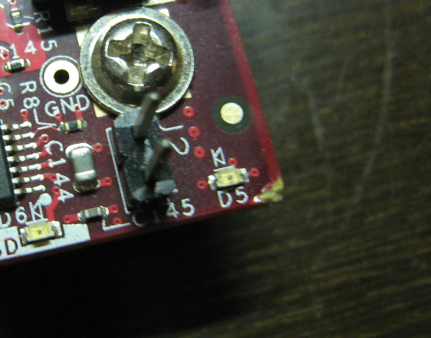
Unknowingly I scrapped a corner of my BBxM (Rev B), PFA image, which might be the reason that D5 power indicator led does not glow. I tested D5 led by DMM but looks it’s friend. Though D14 glows solid on power.
DMM measured 0.9V at D5 anode.
I see a track outlining the board. Is it the 3V3 power track? Since it has been disconnected due to scrap.
Software Setup:
I freshly wrote the Angstrom image to SD Card (formatted using mkcard.txt, copied MLO, uboot.bin, uImage in order to partition 1 and copied and then extracted the Angstrom image and modules on partition 2).
Power Setup:
I’m using a 5V/3A regulator circuit (powered by 9V/2A adapter) to power BBx.
Serial Connection:
Profilic 2303 USB Serial Adapter (115200, 8N1, No flow control)
Knowing all these, please help identifying that why my Angstrom is not booting on BBx.
Thank You,
– Aadeesh S. Bhagwatkar
If D5 is not glowing, then the odds are good that that voltage is missing. That voltage is required. It drives the serial port and the DVI-D interface. The est points and schematic can be found in the System Reference Manual.
Gerald
I measured VBAT as 2.46V which should be 4.2V according to Table 46. VBAT is the input to TPS2141’s LDO_IN and also to TPS65950 which outputs VDD1, VDD2 and VIO_1V8 which are tested 0V.
So VBAT should be brought to nominal voltage of 4.2V.
Doing a continuity test on D5, it does not glow which means it is burnt and I have to replace it.
I’m worried about the track that outlines the board.
Is it VBAT?
Could it be that huge metal washer is grounding something?
ril3y
Stand-off’s removed and tested. Still does not work.
I am thinking to remove enough silkscreen from the top of outlined track and solder a bridge wire.
Should I do it?
Sounds like if the VBAT is that low, you have zapped something.
Gerald
The corner shown in the pic attached to my initial post is the only seen physical damage.
What do you think that “something” might me?
Doubt its the corner damage. I honestly think that the stand offs were the issue and ‘zapped’ something.
Riley
I have no idea. Maybe electrical. I cannot tell what may be wrong without looking at the board and applying probes and debugging it. My experience says that the regulator is most likely blown, but it could be other things that caused that.
Gerald
Doubt its the corner damage. I honestly think that the stand offs were the issue and ‘zapped’ something.
I used BBx for several times with stand-offs with no problem. But used the power circuit for the first time.The circuit guarantees 5V output and uses UCC283-5 regulator from TI.
My experience says that the regulator is most likely blown, but it could be other things that caused that.
With this statement and the test voltages, I’m thinking the same.
So, should I bury BBx? But it has some life. 
Only reason I thought that was I did that very thing. Fried the board with some standoff’s.
Riley
I should kept that in mind too.
But I should identify the problem just like you did.
Mr. Gerald can I get some local (Bangalore, India) assistance to debug my BBx?
You can try the Tenet or the IDA folks. But I don’t expect therm to be able to repair damaged hardware for you.
Gerald
As expected. Even if they provide some debugging help I would be happy.
If there is no voltage there it most likely will not boot. You need to get the voltage there on the output of the LDO. That generally entails replacing a part and see if it fixes the issue. There is no magic solution here.
Gerald
Ok. Thank you for providing the directions. I will update this post if I find a solution.