I’m not sure that I understand the difference between the Beagleboard forum and the Beaglebone forum, but thought I would try posting here as well.
I have a Beaglebone Blue connected to a GPS module via the GPS micro JST connector. I selected this one because it has +5v, which is what is needed for my GPS as opposed to 3.3v on the other UARTs.
The GPS module works correctly, but my issue is I can’t power it down. It’s been suggested that the 5v rail can’t be shut down with the battery connected, but that seems rather odd to me. The also suggested solution was to use a transistor to switch 5v power via a 3.3v GPIO pin. I suppose that’s a solution but not a very elegant one if the board can be somehow configured to power off the 5v rail. It seems like this should be possible, albiet not easily accessible. There doesn’t seem to be much/any documentation available about this at all.
I made a Youtube video showing what’s going on;
https://www.youtube.com/watch?v=9xrXKRy97Yk
Any suggestions appreciated, otherwise I think I’m going to have to go down the path of the transistor relay…
Sir,
Seth here. I just got done dealing w/ someone on this subject. The 5v pin from the GPS connection cannot be "un"powered. It stays powered on while the board has power.
Seth
P.S. Try UART instead at 3.3v. This may help.
Hi Seth, I really appreciate the reply.
I was afraid of that. My GPS module requires +5v. Is there another +5v source on the board that is switched off when the board powers down? What about the black power connector above the GPS UART port?
Otherwise it looks like I will be building a resistor circuit and triggering it from a GPIO pin.
Hey Mr. Dan,
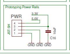
Seth here. Yep. That 5v only stays on. That black connector is rated at 5v and 3.3v. It does not power off either. See here:
Seth
P.S. From what this fellow told me, those two connectors are used for power but that neither powers down if power is still applied to the board.
Hello,
Seth here, again. I know this may seem odd but that is how the board was produced. They may make another one at some point. Who knows? For now, a button could work. That would take some extra oomph, though. If you want, I can try to help on this matter.
Seth
P.S. If you have any electrical set up you want to share on your idea, I can try to alter the schematic or think of another way.
Sir,
I just found a source for ideas: https://next-hack.com/index.php/2017/09/15/how-to-interface-a-5v-output-to-a-3-3v-input/. Adding a button and software could prove valuable. If anything, it may help a bit.
Seth
P.S. GPIO works for buttons, LEDs, and other circuitry. I am sure you know how to do things. I was trying to latch on to learn more. Sorry.
No apologies needed, I’m just trying to figure this out. What I meant was using a GPIO pin to trigger the relay/transistor which would then switch on +5v.
I’ll take a look at the links above, appreciate your help!
Hey Man,
Seth here. Did you ever figure out the issue w/ setting up a GPIO pin to control the 5v for your GPS?
Seth
I’m kind of at a standstill. I found a circuit design to use a transistor to take a 3.3v input, and switch on the 5v for the GPS but then while doing more reading someone said that was a really bad idea because they weren’t opto-isolated. I didn’t really know what that was, but after reading it makes a little more sense. If the transistor fails or is otherwise damaged, it could end up feeding 5v into the 3.3v section of the Beagleboard and fry it.
I was looking for an opto-isolated transistor relay, found one but haven’t gotten one ordered yet to try it out.
That’s pretty much the status, I was going to try and talk to an electrical engineer friend of mine to see what he thought of the situation. What do you think?
Thanks,
Dan
On Wed, 13 Feb 2019 20:57:02 -0600, Dan Hammans
<dan.hammans@gmail.com> declaimed the
following:
I was looking for an opto-isolated transistor relay, found one but haven't
gotten one ordered yet to try it out.
You can fake one using an LED, Photoresistor (or other simple
light-detector) and some heat shrink tubing. Slip LED and sensor into
tubing so the "noses" touch, and heat the tubing to hold them in place...
LED to RPi, sensor to transistor switch.
Hello,
While reviewing this info. you provided, an optocoupler might just work. I found a site that sells them but I also found on that site, some datasheet. See here for the datasheet: https://www.analog.com/media/en/technical-documentation/data-sheets/ADuM1200_1201.pdf.
Seth
P.S. I have not tried this conversion yet so my mind would say take time. Do not rush if possible. Oh and from what I understand, the optocoupler works by shutting off instead of transferring the signal any further. The DigiKey site has some and I found one that is unidirectional: https://www.digikey.com/product-detail/en/analog-devices-inc/ADUM1201AR/ADUM1201AR-ND/725709&?gclid=CjwKCAiAwJTjBRBhEiwA56V7q0A4N0DBiSwt5Wm4ahl6pdiosiiP-YLgdJr-Y9oH2wYF3XcMOvw7FBoCLmoQAvD_BwE. That datasheet above is the sheet for this link.
You guys are great. I’m going out of town for the weekend so I’ve ordered a couple of the parts suggested to give it a try. Should be here when I get back.
Thanks!
Dan
Also, it has been EONS since I’ve seen a netcom.com address. That’s cool :).
Hello Again Dan,
Seth here. I am currently working on a Flying BBBlue, too. At least, I thought this is what you were working on. I have arducopter on my BBBlue, some .service files to boot some specific commands, and I am trying to pair a receiver as of now.
…
If you are not using the BBBlue for flying, sorry for elongating my post. But if you are using the BBBlue to fly, we may be able to use each other. Who knows?
Seth
P.S. The only steps I need to take to complete my project is to pair the transmitter and receiver and then I need to power my ESCs. I guess I need to calibrate the ESCs, too. Anyway, good flying and if you have time when you return, shoot a post to let me know about the BBBlue excursion.