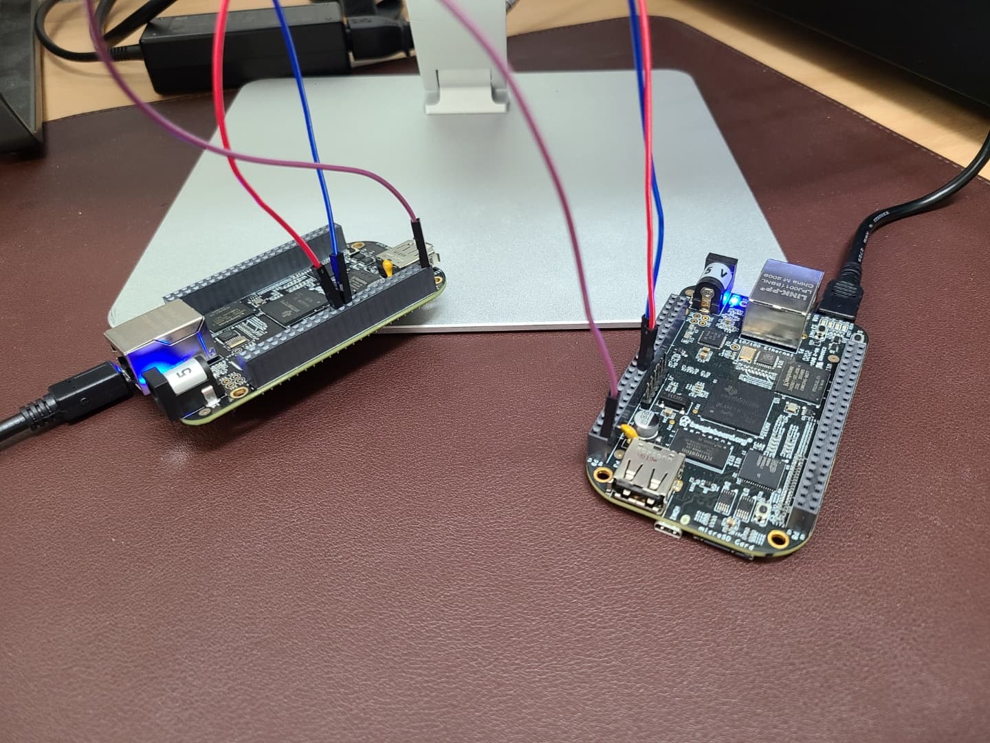
I think you need to study the CAN bus and CAN transceiver data sheets to get a better understanding of how exactly CAN works.
It’s a network using CSMA/CR which means Carrier Sense, Multiple Access with Collision Recovery.
That means that at any time multiple units can transmit at_the_same_time. Connecting a devices Tx to another device’s Rx doesn’t come close to handling that if you added a 3rd BBB so trash that concept.
Forget for a moment about transmission lines. How would you connect multiple transmit lines together so that any one device can assert a signal (let’s call it a dominant signal) on the bus. The easy way to do this is to use NPN open collector devices which switch on when the base of the transistor has current flowing into it; the device output logic high from an inverting driver.
Now each device can pull the signal low. Of course if they all did this then the signal would stay low and we wouldn’t know who was causing this. So we connect the Rx pin to that same collector pin (pulled to +3V through a resistor in the case of the BBB although better to isolate with a level translating buffer).
Now when the bus is idle the signal is brought to the pull up resistor high voltage because the Tx Pin is high. The Rx pin, through the buffer sees a high on the bus too. Notice that the Rx is always aware of what’s on the bus.
So when a device asserts the Tx line it turns on the transistor and pulls the bus to about 0.6V. The buffer on the receive side reflects that back as a logic low matching the transmit side. So far so good.
Think about sending 1’s and 0’s. This open collect bus now reflects those 1’s and 0’s. As long as only one device is sending it all works but we do have Multiple Access with lots of devices so how do we deal with this?
We first check to see if anyone else already has the bus active and if so we wait until it’s been inactive for at least say 7 bit periods. That’s called Carrier Sense going back to the days when data modulated a carrier frequency. If it’s been quiet for that long we can assume that no one is using the bus so we can send our bit stream which we do one bit at a time of course beginning with a dominant bit called a start bit.
If 10 devices are all waiting for that 7 bit bus quiet period and they all want to send then they will all start sending that first start bit at the same time and it will be exactly the same length. So how do we know when multiple units are sending at the same time. In the old Ethernet with CSMA/CD where CD stands for Collision Detection and if the receivers read back the opposite of what they sent they all terminate and delay for a ‘random’ period before they try again. So the likelihood of them colliding again is much less until there are too many devices on the bus. It’s why the older RG58 coax Ethernet could reach 50% bus usage before it became worse.
The CR stands for Collision Recovery. The arbitration period is the ID part of a CAN message. During that time each device checks inside each bit period to see if what it sends matches what it reads. If it doesn’t match it switches over to receive the rest of the ID part and then the rest of the message. Nothing is discarded.
The winner during that arbitration period is the one who’s output signals read by the Rx pin matched what it had on the Tx pin. All other devices switched over to receive the message and that’s why CAN bus can have 100% utilization of the bus.
This explanation is just a small part of the CAN protocol and doesn’t address the error checking or bit stuffing. But if an ID like 030 is sent it’s a bit pattern 00000110000 where the zeros are the bus in a dominant state (transistor driver ON and the ones are recessive, transistor driver OFF).
Hopefully this helps you understand.
John Dammeyer
