I followed the steps provided and checked /dev/ folder. I can observe the spi - spidev1.0, spidev1.1 interface.
root@beaglebone:~# ls -l /dev/bone/spi
total 0
lrwxrwxrwx 1 root root 15 Feb 3 14:48 0.0 → …/…/spidev1.0
lrwxrwxrwx 1 root root 15 Feb 3 14:48 0.1 → …/…/spidev1.1
I think I can able to write into spi interface but couldn’t able to read it. Seth Have you connected any spi Hardware and accessed it? Still, I couldn’t access the SPI Hardware.
Don’t know what’s going wrong. Let me revisit once again and check.
In previous posts say I tried adjusting using overlay but with am5729-beagleboneai-roboticscape.dts.
I have not connected any SPI device yet. I will have to try soon. I am sorry but this is as far as I got on this idea so far.
Seth
P.S. I think I have a SPI Cam around here somewhere. I can try. This will not happen right away but in the meantime, I can do the loopback tests on each/different SPI peripheral on the BBAI.
@Mahaboob@silver2row were you able to get the SPI interface enabled on BBAI? I am putting together a cape and want to add an Everspin MR25H256 MRAM chip. I can’t seem to get the SPI interface enabled at all. If I can get it working I will port the std Linux Everspin driver to 4.19 or 4.14 which ever I can get to work.
Not so far, i.e. as I do not have any testing module for SPI right now. I am not sure what @Mahaboob found so far after building and changing things in his personal DT file.
Seth
P.S. I should get around to it soon. @jostmp , I am looking into getting some type of hardware for testing soon. I will plug it in to the ole oscilloscope and try it out. Be ready for some odd photos of SPI functioning and also…
You can always do the loopback test of your SPI device by shorting the COPI CIPO pins.
I have been using the HiLetgo cheapy SPI logic analyzer(about $12) with Sigrok (Shareware)for a couple of years. Better than chasing SPI with a 2 channel o-scope. I will keep pushing on the SPI interface. If I get something working I will post it.
Hello…I promised some funny photos for loopback test and Chip Select. I cannot decipher them right now but I will update you soon. Also, /dev/spidev1.0 works in the loopback test on the AI.
Seth
P.S. Here is a photo w/ the CS line and CLK source on the /dev/spidev1.0 interface peripheral due to ExploringBB from Molloy’s book in Ch. 8 and his driver.
So, it seems when CS goes high, the CLK is doing business under the hood.
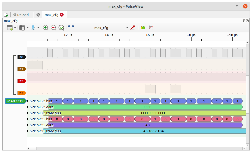
CS is most times active low. But not always. anyway if you are capturing with a two channel clock and data are what you usually want to see. I captured this for a bit banged SPI on PRU1_1. This is a screen capture from sigrok pulseview with the HiLetGo logic analyzer. You can see all four pins. CS goes low, clk starts driving, and MOSI data appears on D3.
Yes, that is bit banging a SPI interface to a Maxim Integrated device using PRU1_1 pins P8.13,15,16,18. I am trying to enable Linux SPI interface to eventually read/write an MRAM chip from user space.
I mean…from what I can tell, the devices are listed from the details of Bone-Buses if you add in the respective .dtbo files in the /boot/uEnv.txt file.
Seth
P.S. I am using P9.28/29/30/31 on the AI now for loopback from Molloy’s book.
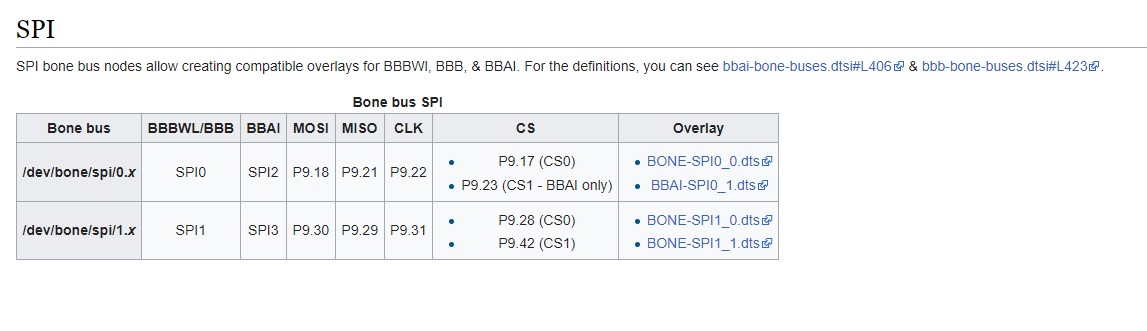
/dev/spidev1.0 is P9.17/18/21/22 and /dev/spidev2.0 is P9.28/29/30/31. I am pretty sure.
Seth
P.S. Try the instructions. At least for me, it worked. I can test w/ my o-scope which probably needs a source update. Blah. But soon after this update, I can get some more ideas out.
show-pins list the spi pins as active.
P9.18a 242 fast rx up 0 spi 1 d0
P9.21b 241 fast rx up 0 spi 1 d1
P9.22b 240 fast rx up 0 spi 1 sclk
P9.23 237 fast rx up 3 spi 1 cs1
CLK, MOSI, & CS all showing active on my analyzer. Connecting P9.18 → P9.21 would achieve loop-back if you are using an app that writes and reads.
for folks that are having headaches with kernel hanging (BRICK) when loading a new overlay I found a quick work around.
need serial cable to access u-boot console
press space bar at startup to get u-boot prompt.
then edit capeloadoverlay environment variable and remove run loadoverlay;else from the command.
=> editenv capeloadoverlayif test -e ${devtype} ${bootpart} ${uboot_overlay}; then run loadoverlay;else echo uboot_overlays: unable to find [${devtype} ${bootpart} ${uboot_overlay}]…;fi;
delete that phrase hit enter, type boot, hit enter
=>boot
this allows the board to boot without loading the overlay. Fix overlay or edit your uEnv.txt to remove the overlay.
This has saved me a bunch of time. As you well know it is real easy to hang the BBAI with an overlay it doesn’t like.
 I will keep pushing on the SPI interface. If I get something working I will post it.