And looking at the ULN2003, you’ll need a charge pump of the high voltage side of the H bridge. Problem is the transistor will only switch if you get the base up to around about the Vdd voltage, for this motor the data sheet mentioned 24V, and at 24V you’ll need a charge pump.
L293D looks closer - but data sheet isn’t clear of you can switch the high side with 3.3V output of the beagle … and reading the data sheet from TI, both the L293 and L293D should work, it can switch the high drive voltage using the TTL signals from the beagle. [N.B. TI says this part has been replaced by the DRV89xx-Q1 chip … and reading that data sheet it includes PWM circuits, that you program over SPI! - what a beast … Acutually do read the data sheet for DRV89xx-Q1 chip, it describes just about everything you have to do - so its good to understand. Note the internal PWM on the chip, can’t do the frequencies you’ll need (e.g. speed of the stepper motor) - and I don’t think can do the phasing you want]
Let me ask a proper electronics friend if there is a suitable bridge chip - he’ll know off the top of his head …
The BBB has 4 PWM outputs availble on EHRPWM1&2 with A&B signals with polarity. The 2 can be synchronized and phased to produce the waveforms for stepper motors. I am not sure if the Linux side drivers are capable of synchronizing and phasing neccessary.
I do know that the PRU’s are capable of accessing the EHRPWM registers directly. I have written code for the PRU’s to control 1 EHRPWM not 2. Their may be existing PRU code to do this. Either bit banging or PWM’s should work well with the PRU’s with communication to the Linux side through RPMsg. I have used PRU0 for the drive and PRU1 for the messaging using shared memory between the 2.
PS: I develope my code on Ubuntu 24.04 using Code Composer Studio CCS 12.8.1 and uploading to the BBB.
And it seems the like kernel (at least on PB2) knows about the PWM. Echo a number to export and it brings up a PWM, where you can set period and duty_cycle - not clear if you can set phase.
So seems like much is available inside linux …
ah - described pwm.txt and you can’t change phase, so you have to do the direct memory writes to the TI peripheral location.
Did some browsing this morning of the BBB TRM spruh73q.pdf - what you want to do is shown in Figure 15-30, Thats a upward going pwm, with both CMPA and CMPB on the single waveform, one to switch on and one to switch off. Doing this on two PWM one starting at 0% and switching off at 50%, and the other switching on at 25% and off at 75%; with both synchronised - then you get the waveforms you need. Changing the period will change the motor speed. Whats also good, is that when you update values, they are buffered till the next reset of the PWM counter. This means you can reprogram the whole change in frequency, and it only gets uploaded at the next period.
As others have point out - problem is the memory management inside unix. Usually this is a very good thing, but for us makes it hard to access the memory mapped peripheral. From what I can see this link gives the method. You’ll probably have to run the resulting executable as root, to get the write access.
With the PRU’s you have direct register access. My struggle is getting the device tree overlay to work correctly. Then hopefully the old code I had to work at least giving me the PWM waveforms on the scope correct. Then I can go back and play with the registers until I get the waveform figure 15-30 of the TRM. For the overlays I will start with the PWM overlays for Trixie kernel 6.18.x and copy them to 5.10. Then get the /sys/class/pwm to work then hopefully on to the PRU code.
I still think brute force bit banging with the PRU’s would be more intuitive and easier, to incorporate:
start, stop, count, and speed into one app. Anyway I am up to the challenge with the PWM’s on this snowy day for a 82 year old.
Hey everyone. I think I may have an idea but it is not going to work with my current set up. Like, @DavidSummers , stated…
I would need a capacitor or some other type of charge pump to handle the L298D and/or ULN2003.
Also, I am going to use a set up of drivers already “made” that will accept GPIO (only).
I will need two GPIO pins to handle a driver. So, six total GPIO pins should be used. Is this possible with the PRUSS?
I appreciate everyone jumping in the tell me what is what and how I should go about handling things.
Also, the omc-stepperonline drivers just get handled by the GPIO from the BBB and/or Pocket Beagle 2.
I know the GP0 and GPI pins on the BBB from the PRUSS can be allocated to handle this idea. Do I know how so far? No. Not yet anyway.
And yes, for me making a driver myself via the L298 and/or ULN2003/2/4, I may never make a Cape to handle this idea. So, I might and will probably stick with already MFG. motion drivers.
Usually what we did in space was specify a driving chip, that included the charge pump, for the upper side of the H bridge. So look at getting a driving chip that does that specifically, e.g. the TI chip mentioned earlier - but I expect there are many others.
If you still to the 3.3V that the GPIO voltages, that will still set up the magnetic fields in the motor, question is will it be enough to pull the stator to the poles. It may work a bit, but danger there is where the stator doesn’t follow the rotating magnetic field, but occasionally falls back a cycle. This will rapidly give a stall.
With GPIO drive only, I must admit I just look at the pins on the outside of the beagle, as a way of getting signals out. The signals may be bit flipping (GPIO), or attached to a PWM, or a UART. Its all just putting waveforms on the pins - and as long as they are what you want - it should work.
Anyway hope it goes well, and that you make progress on the project.
I have tried to get the EHRPWM1&2 to work with the BBB PRU’s with no sucess. Don’t know what changed for kernel 5.10. But for know the only solution would be for the PRU to control 4 gpio’s through register __R30.
I’m half way through code that should work on the BBB, in linux. Need to tie the two pwms together, so they are locked together on timing. Then do a device tree …
I gave up on EHRPWM’s for the PRU’s. Going to work on a bit banger solution for __r30. Need to get the Device Tree working first. Will use the first bits B0-B3 to define the driver output pattern in a table. Then step 0-3 for forward and 3-0 for reversed for the table. The interface will be thru PRU1 for speed, direction, and count. PRU1 will use the RPMsg protocol and communicate to PRU0 through shared memory. All the bit banging and delays will be with PRU0. Compensation for code overhead will be handled through a calibration process then placed in shared memory, which is being used for - speed, direction, and count.
I am attaching my overlay that I use to work with LINUX through the /dev/bone/pwm interface. If it works for you you should get /dev/bone/pwm/0 & 1 with both a&b exported.
Interesting. Did you use TI SysConfig to do the device tree? I’ve just done it myself and for my AM3359 CPU (which my BBB has) and it says use MUX_MODE1 and 2 for the eHRPWM. I need to check if these are on the header pin outs, don’t seem able to direct to other pins. Hopefully finish code in a day or so, just reading the AM335x TRM - which you need to be very careful reading to get things right. Hopefully though test soon - but I’ll have to PWM frequency down very low, so I can test with LEDs …
Oh yes I’ve only done pin outs for A and B, and not the other outputs - I may well disable B, as I need to use both the A&B comparators to be able to do phasing correctly.
I use a spread sheet that was done years ago for P9 & P8. They have the pin-mux register addresses associated with the PIN number. I then look up in the - include/dt-bindings/pinctrl/am33xx.h for the macro associated with the address. The mode is also listed in the spread sheet.
Interesting, On the PB2 so AM62xx processor, I searched for how to get the PRU pins out, and the mode to set the pins - could only find it in TI SysConfig. I’ve not tried the same with BBB/PB and the AM33xx chips … I’ll search for the spreadsheet and compare to SysConfig. btw for the AM62xx looks like the mux was right to get the PRU out - or rather, I have 4 flashing LEDs on 4 of the PRU outputs - next to test if they are what they should be …
I have used the SK-AM64B where I can use JTAG with CCS 12.8.1 to develop code for the EHRPWM’s. It has been several years since that time, so I don’t remember alot. I also ran Linux on the AM64B with cobbled up device trees. I used SysConfig for that. I can also use SysConfig for the am3358 ZCZ on the BBB that I have, cut and paste also.
I will attach spread sheet I have used for years for the BBB.
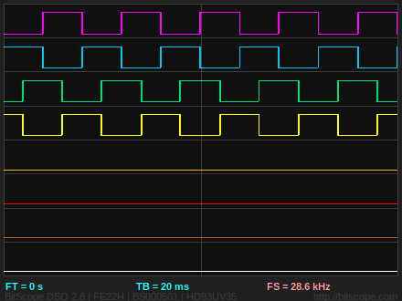
Waveforms for BI-Polar stepper using PRU0 on the BBB. One is for forward direction and the other reverse at 100 steps/second. Next step is to use PRU1 for the RPMsg control interface with Linux debian Trixie kernel 5.10.168-ti-r83. Pru outputs are on: r30_0 P9_31, r30_1 P9_29, r30_2 P9_30, and r30_3 P9_28.
Ah yes mean to say - so you decided to do Not-A and A, and Not-B and B separately, which makes sense if you don’t have a bridge. Did you check with the manufacturer you can do this? It only showed Not-A as the opposite of A …
Since my output to the driver uses B0 - B3 in a uint32_t step[4] array it is very easy to create any step sequence I want. To go backwards all I have to do is reverse the indexing of the array.
I will be using a Drok 7a/160w dual H-Bridge, SKU:200206 that uses L298 logic. It also has a PWM/ENABLE input which could be used for more speed with higher bridge voltages.
Just got my step motor. Looks like I need to change the step sequence.
New sequence is: 0x05, 0x06, 0x0A, 0x09
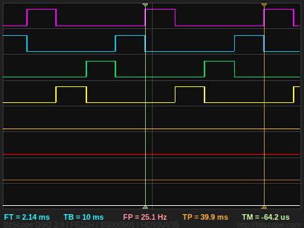
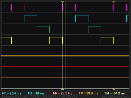
Now looks like what you would expect from EHRPWM1A and 1B opposite polarity and
EHRPWM2A and 1B opposit polarity phased with EHRPWM1 90 degrees.
Since my power supply output is 12V I am going to add a pwm signal to my Drok driver’s PWM/Enable input. Going to use the PRU1 and the APWMO at 100 Khz. The resistance of my motor is 1.4 ohms I would quickly exceed 2.0 amps. So assuming no voltage drop across the H-Bridge transistors and a 13.6V output from the power supply I will set the duty-cycle to 25%.