I’m new in beaglebone black. I know in original version beaglebone, I can get serial debug information just plugging mini usb to pc. But Beaglebone black can’t. I search from http://circuitco.com/support/index.php?title=BeagleBone_Black_Accessories and try to use Adafruit 4 Pin Cable (PL2303) by plugging green line to P9-4, white line to P9-5, black line to GND. I use putty trying to get serial information but I can get only much of disorder and non-meaningful characters just like setting wrong baud-rate. But I don’t know why I set 115200 in putty and it work in original version beaglebone. How can I get right serial debug information in Beaglebone Black. Thanks.
You need to connect to J1, not P9…see the SRM (System Reference Manual) at http://circuitco.com/support/index.php?title=BeagleBoneBlack#Hardware_Files
Make sure cable’s RX is connected to BBB’s TX and cable’s TX is connected to BBB’s RX.
-Dale
Or just look at this simple picture i made around two months ago.
Hello people,
I too faced the same problem, but with a simple solution. The BBB board(REV A5C) does not work correctly with direct TTL to USB conversion. Use a Level conversion logic between the Board and use a RS232toUsb converter to get the debug messages.
thanks,
Vivek
Hi,
I used one of these cables:
https://www.sparkfun.com/products/9717
and it plugs in directly to the 6 pin connector. I wrote up a web page on creating a right-angle connector which shows the cable plugged in:
http://www.davehylands.com/Electronics/Debug-Connector/Small/12-Installed.html
It’s important to use a 3.3v USB-serial converter.
One of the posters mentioned P9-1 P9-4, P9-5. P9 is the big 46 pin connector (female). You want to use J1-1, J1-4, and J1-5 (i.e. the 6 pin connector with male pins).
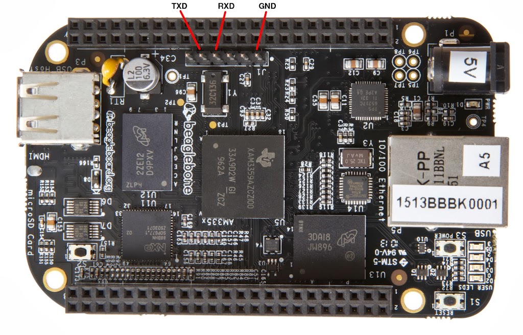
Here’s a picture William Hermans posted a while ago that labels the pins quite clearly:
https://lh4.googleusercontent.com/-3oca40vrH-g/Ubd5TjD-0_I/AAAAAAAAALU/-GibZBaTvKk/s1024/beaglebone-black-serial.jpg
Hello ,
I purchased the ttl to usb convertor and connected with board but it is not getting boot up .kindly suggest where i am going wrng.
For making kernel image ,rootfs , .i followed the procedure given in beyondlogic site.
Oh, Lord… I wasted one whole day trying to figure this out. Turns out I connected Rx to Rx and Tx to Tx.
Thank you, Dale Schaafsma.
Oh, Lord.. I wasted one whole day trying to figure this out. Turns out I
connected Rx to Rx and Tx to Tx.
Find an RS-232 LED monitor. You want something that monitors the
state of each line, and shows you a red or green light depending on
the state of the line. I have seen them in 25 pin versions, but you'd
likely want a 9 pin version.
Connecting that up to each device in turn shows you which line is
drive, and which is not.
There's DTE (Data Terminal Equipment) and DCE (Data Communications
Equipment) (IIRC), they have different signals on different pins,
since the original idea was that they'd be able to be wired pin to pin
to function. DTE was supposed to be a terminal of some sort, DCE was
the external modem.
Now that your computer could be both, there's a connection problem.
Been there, done that.
Harvey
Thanks for the tip, Harvey. Will try to find one at a local store. Funny thing is, the pl2303 I bought was a cheap knock-off(~2.5$ in India) and I didn’t know if the LEDs on it actually worked. As I found out later, there is a green LED on it that lights up during communication. Finally some progress on my BBB!