I need a clock signal for the LT8500 pwm chips and it would be nice to use the clock output on the beaglebone rather than an external oscillator. My guess is that it runs at the 24Mhz clock on the beaglebone which will work for the LT8500s but I don’t really care what frequency it is for my application. I’m driving DC motors so a few kHz is all I need really. The LT8500s divides the clock frequency to create the PWM frequency. For example, an input of 25Mhz gives a 6kHz PWM signal on all 48 outputs. Just out of curiosity,
- Is the clock frequency configurable?
- Can any of the GPIO pins be configured to produce a clock signal?
- If so, what frequency ranges?
- I read somewhere about timers. How do those work?
I quickly searched the Technical Reference Manual but I didn’t see anything about the clkout2 pin or the timers. Is there another reference I should look at?
Thanks!
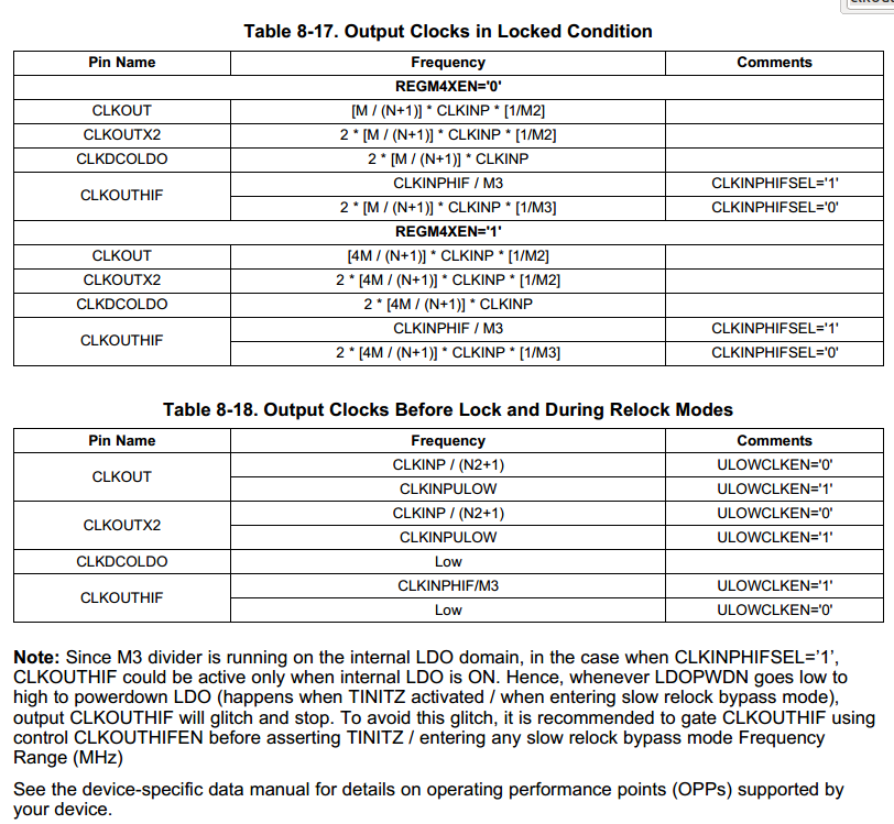
So I did a little searching and found some help in the documentation for the processor http://www.ti.com/lit/ug/spruh73j/spruh73j.pdf on page 880. It shows a formula for the frequency but I don’t understand the M and Ns. It has something to do with the phase locked loop and creating a super high frequency clock using some fancy circuitry and I really just need to find the default values of M and N to confirm that the output will be around 24Mhz. Can anyone interpret this documentation to give me a better idea of what I can expect on the CLKOUT pins on the beaglebone black?
Gregory,
You can probably use the 24.576 MHz output of the HDMI oscillator that is available on P9 pin 25. The oscillator is enabled by GPIO 1-27, so you can enable using this output it even if you have disabled the HDMI output for some reason. It should be enabled by default.
If you use this oscillator output, you can’t use GPIO 3-21 since they share the same expansion header pin.
HTH
Dennis Cote
I suggest that you look at output pins TIMER4, TIMER5, TIMER6, and TIMER7 (section 20.1.2.4 of the Technical Reference Manual). Those timers are clocked at 24MHz, have programmable divisors, and can produce output clocks up to 12MHz. Section 20.1 of the Technical Reference Manual provides more information on the timers and the datasheet will detail the settings required to associate a timer output with a pin.
I think the simplest solution will be to use the HDMI oscillator pin since 24Mhz is perfect for the chips I’m driving. It is difficult to find simple answers in the documentation so thank you thank you both for your help!
Sorry for the confusion, I used someone else’s e-mail to reply to you all. Thanks again!
What frequency do you want? first of all what you need to know is the frequency of CLKIN. Best I can tell that defaults to 24Mhz. from there you can pretty easily find values to fit closely what you need for clock output frequencies. For that matter if you’re unsure write a loop that produces a table of values for a given CLKIN frequency. in generating such a table using a CLKIN frequency of say 1MHZ could work quite nicely as the values can be easily scaled from such a table.
Eric