Sorry, but I’m not letting you get away with that comparison @jkridner  .
.
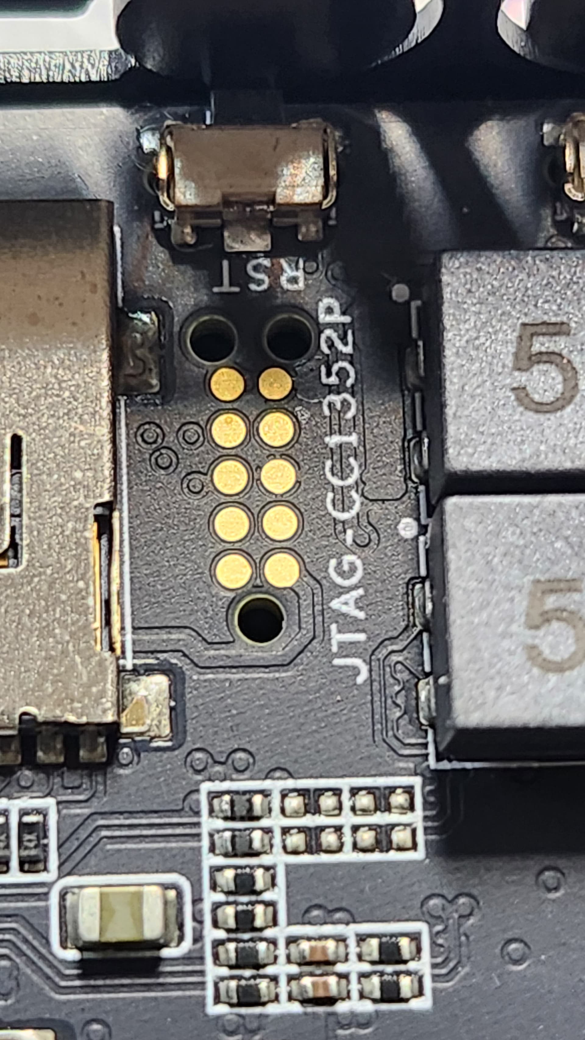
My experience is that the Tag-Connect without clips is quite unreliable for development work without a custom jig to hold things in place. It’s fine for one time programming tasks or a rare firmware update, but for debugging it just doesn’t work reliably even for much smaller SoCs. Even our holding jigs had to go througn several iterations to make it “reliable enough”.
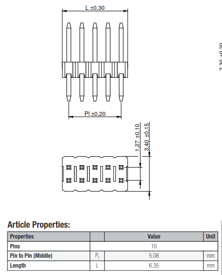
So, a “real” comparison is against the Tag-Connect with clips. A footprint for a “full” 10-pin through hole is 6.4mm long x 3.4mm wide. (21.7 mm^2) A footprint for a “full” 10-pin SMT connector is 6.4mm long by 6.3mm wide (40.3 mm^2)–the advantage being no through holes to obstruct other layer routing.
See: https://media.digikey.com/pdf/Data%20Sheets/FCI%20PDFs/Minitek%20127_Catalog.pdf
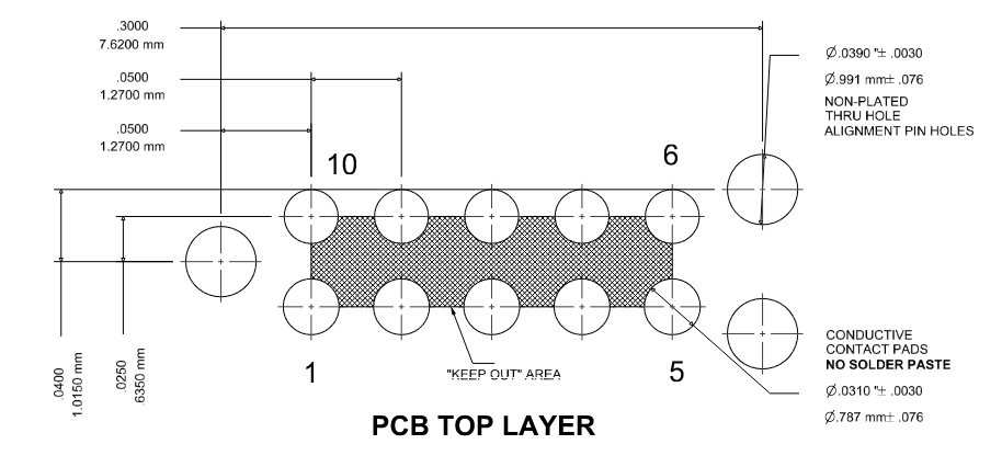
A Tag-Connect without clips is 7.62mm long x 2.069mm wide (15.7 mm^2). A Tag-Connect with clips is 8.91mm long x 7.62mm wide (67.8 mm^2).
My smattering of dev boards concurs with this. Their one-shot interfaces are either 10-pin SMT .050", Tag-Connect, or custom solder pads. However, their debug probe interfaces are all 10-pin SMT .050" with one exception that is Tag-Connect with clips.
I’m a big believer in .100" through hole. However, if you simply can’t stomach that, then the standard CoreSight 10 10-pin .050" ARM debug connector is really the way to go for debug ports.
I do understand that part of this is cost transfer as everybody continues to get stung by everybody whining that the RPis are “cheaper” than a BeagleBone in spite of them being totally unavailable (I sympathize). So, you’d like to 1) not populate the footprint but 2) allow people to run a debug probe on these boards without having to pull out a soldering iron and 3) only charge those people who are actually using a debug probe. Only a Tag-Connect with clips hits that point.
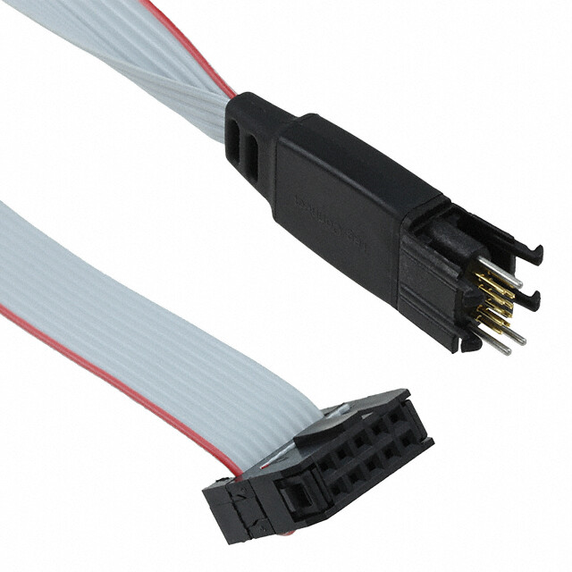
Unfortunately, the Tag-Connect cables are sufficiently expensive (about $50) and fragile that I just see you irritating everybody. Those of us who are used to this will just roll our eyes and buy the cable and wish you’d used a standard .050" connector. Those who aren’t used to this will probably duck the cable and try to solder to the pads anyway to save the $50. And those who need reliability will pull out a soldering iron to avoid the problems with Tag-Connect.
So, the only people who would be well-served are those who aren’t sensitive to a $50 cable and don’t easily lean into soldering on a connector. In return you are inflicting a slightly flaky debug connection on them.
You have better feedback on this than I do, but I’m just not seeing this.