As long as it is found shouldn’t matter where it is. I would imagine the import will fail if it can’t be found.
Right,
I will put it in PATH anyways. Maybe this could be the issue.
Seth
Hello Sir,
I am out of ideas. The barrel jack is connected. You know something…
- The sys_5v powering the Cape on the top, not from the vdd_5v from the bottom, might be working but…
a. I have a loose connection at the blue +/- connector. I will resolder it to see if this is the issue. - And…when I use the .dts file, it faults out on output w/ a lot of errors.
Seth
P.S. I will return service once the Cape has been resoldered and the blue connector is better situated.
Sir, Seth here again. So, I have been curt and tempted more by the source before “us.” So, I keep trying new routines and ideas. I know what you said about the gpio68 pin is firstly input.
So, I set it to output. I then call value to 0 or 1 via B_PWM1 = pathlib.Path("/sys/class/gpio/gpio68/direction") and then call B_PWM1.write_text("out").
I tried w/ writing the value to 0 and then to 1.
Neither are working (from what the output is telling me by the Servo Motor not moving). I have a Oscilloscope here I can see if things are returning the correct timing and waves.
But…It can only handle 1 GHz maximum. It is dual channel.
Seth
P.S. I attached the DMM to the 5v and GND connector on the ServoCape. I am receiving the power and the output states 5.10v.
Anyway, if you think I have gone overboard trying to make this work, please let me know. Oh!
#!/usr/bin/python3

from PCA_1 import *
from time import sleep
from pathlib import Path

i2c_bus = SMBus("/dev/i2c-2")
pwm_controller = Pca9685(i2c_bus, 0x7f)

B_PWM1 = Path("/sys/class/gpio/gpio68/direction")
B_PWM1.write_text("out")
B_PWM2 = Path("/sys/class/gpio/gpio68/value")
B_PWM2.write_text("0")

pwm_controller.set_pwm_frequency(50)
pwm_controller.set_servo_angle(16, 90)
sleep(2)

def cort():
    B_PWM2.write_text("1")
    for l in range(1, 10, 2):
        pwm_controller.set_servo_angle(16, 0)
        #pwm_controller.set_servo_angle(15, 0)
        sleep(2)

        pwm_controller.set_servo_angle(16, 90)
        #pwm_controller.set_servo_angle(15, 90)
        sleep(2)

        pwm_controller.set_servo_angle(16, 180)
        #pwm_controller.set_servo_angle(15, 180)
        sleep(2)
cort()
sleep(2)
The line i2c_bus = SMBus("/dev/bone/i2c/2a") has been altered in this file to show "/dev/i2c-2" in this file and in smbus2.py (which controls the path directly in an absolute way).
Aw! If you have any feedback, I would (need) like to hear it or read it.
Hello,
Okay…
So, i2c is a file. I am moving in loops now, i.e. so I am reiterating. But…if the file does not have any other files w/in it, how am I supposed to communicate to it?
Seth
P.S. Those libs? Or…would I use a specific address in bytes (if that makes sense, phew)?
Hi Seth, ok a couple of things.
Firstly I am not doing any error checking in the set_servo_angle() function.
The PWM channel must be from 0 - 15. Writing to 16 will have unexpected results.
Potentially overwriting the mode1 register and turning of auto increment, causing all further pwm writes to fail.
B_PWM2.write_text(“1”) ← this will disable all PWM channels.
This is confusing.
Are you actually using SMBus(“/dev/bone/i2c/2a”) in your code ?
Does /dev/i2c-2 not exisit ?
Okay,
I will try to use /dev/i2c-2 instead now. I was using /dev/bone/i2c/2a but it was not working. I will try 0 - 15 instead for now on.
I will use write_text("0") for now on.
/dev/i2c-2 does exist.
Seth
Hello Sir,
Okay…I am using /dev/i2c-2 now. I am still not receiving any output via motor movement.
This source here just stalls the output:
#!/usr/bin/python3

from PCA_1 import *
from time import sleep
from pathlib import Path

i2c_bus = SMBus("/dev/i2c-2")
pwm_controller = Pca9685(i2c_bus, 0x7f)

set_pin = Path("/sys/class/gpio/gpio68/direction")
set_pin.write_text("out")
set_pin = Path("/sys/class/gpio/gpio68/value")
set_pin.write_text("0")

pwm_controller.set_pwm_frequency(50)
sleep(1)

def cort():
#    for l in range(1, 10, 2):
    while True:
        pwm_controller.set_servo_angle(15, 0)
        #pwm_controller.set_servo_angle(15, 0)
        sleep(2)

        pwm_controller.set_servo_angle(15, 90)
        #pwm_controller.set_servo_angle(15, 90)
        sleep(2)

        pwm_controller.set_servo_angle(15, 180)
        #pwm_controller.set_servo_angle(15, 180)
        sleep(2)
cort()
sleep(2)
print(pwm_controller)
Anyway, I am going to back up all my files and try to install a .dts file for i2c.
Seth
Hello @benedict.hewson ,
Okay and so…
I upgraded to kernel 4.19.x when this ServoCape in question was working. It still works w/ kernel 4.19.x.
I put in the u-boot_overlay of BBORG_SERVO-00A2.dtbo and rebooted. The source works, sort of.
I am receiving a move to 0 but I think my servo motor is backwards and it just jitters. I will keep testing.
Seth
P.S. Here is the updated source to test:
#!/usr/bin/python3

from PCA_1 import *
from time import sleep
from pathlib import Path
from smbus2 import SMBus

i2c_bus = SMBus("/dev/i2c-2")
pwm_controller = Pca9685(i2c_bus, 0x7f)

set_pin = Path("/sys/class/gpio/gpio68/direction")
set_pin.write_text("out")
set_pin = Path("/sys/class/gpio/gpio68/value")
set_pin.write_text("1")

pwm_controller.set_pwm_frequency(50)
pwm_controller.set_servo_angle(15, 10)
sleep(1)

def cort():
#    for l in range(1, 10, 2):
    motion = int(input("Please enter in your value of 0 to 180: "))
    while True:
        if motion <= 180 and motion >= 0:
            set_pin.write_text("0")
            pwm_controller.set_pwm_frequency(50)
            pwm_controller.set_servo_angle(15, motion)
            sleep(2)

            pwm_controller.set_pwm_frequency(50)
            pwm_controller.set_servo_angle(15, motion)
            sleep(2)
        else:
            pwm_controller.set_pwm_frequency(50)
            pwm_controller.set_servo_angle(15, 0)
            sleep(2)
try:
    cort()
except KeyboardInterrupt:
    print("Done...")
    set_pin.write_text("1")
Issues:
- I do not see the servo listening to commands (yet).
- It turns on/off at command but does not go to the requested angle (yet).
Hi @silver2row ,
I assume you are not getting any IO errors, so that probably means you are talking to the chip.
You can double check by adding a little debug to your code
#!/usr/bin/python3

from PCA_1 import *
from time import sleep
from pathlib import Path
from smbus2 import SMBus

i2c_bus = SMBus("/dev/i2c-2")
#debug
print( "{}".format(i2c_bus.read_byte_data(0x7f,0)))
print( "{}".format(i2c_bus.read_byte_data(0x7f,1)))
print( "{}".format(i2c_bus.read_byte_data(0x7f,254)))

pwm_controller = Pca9685(i2c_bus, 0x7f)

set_pin = Path("/sys/class/gpio/gpio68/direction")
set_pin.write_text("out")
set_pin = Path("/sys/class/gpio/gpio68/value")
set_pin.write_text("1")

pwm_controller.set_pwm_frequency(50)
#debug
print( "{}".format(i2c_bus.read_byte_data(0x7f,0)))
print( "{}".format(i2c_bus.read_byte_data(0x7f,1)))
print( "{}".format(i2c_bus.read_byte_data(0x7f,254)))
The very first time you run this after a power up, you will get 17,4,30 for the first 3 prints and then 32,4,130 for the next 3. If you run the code again they will both be the same, until power is removed to reset the PCA9685 chip.
If that is the case, then you are talking with the PCA9685 chip.
I would also suggest, to add to the write_regs() just to double check you are writing reasonable values.
    def write_regs( self, reg, values ):
        assert reg in range( 0, 256 )
        print("{} {} {}".format(self.addr, reg, values ))
        return self.bus.write_i2c_block_data( self.addr, reg, values )
Double check with a DVM, that writing 1 to /sys/class/gpio/gpio68/value sets the pin high and writing 0 sets it low. If this is not the case then the PWMs won’t work.
The jitter you are getting on the servo motor and moving to 0 might be caused by no PWM signal.
I suggest disconnecting the servo motor and attaching a scope to the PWM pin and see if you have a signal. You should see a high pulse between 1ms and 2ms long, repeated every 20ms (assuming 50hz)
1 Like
Hello,
I am not quite sure what those debug statements are for just yet. When I run the source w/ the debug/print statements, this happens:
32
4
130
127 0 [32]
127 0 [48]
127 254 [130]
127 0 [32]
160
4
130
Please enter a number from 0 to 180: 90
127 61 [184, 11, 235, 12]
127 61 [184, 11, 132, 12]
Please enter a number from 0 to 180:
The buzzing has stopped and now I receive no output, i.e. no jitter and no movement whatsoever.
Seth
P.S. I will get the oscilloscope out and the DMM and test things to see if indeed the gpio68 pin is OE and working. And…I changed up the source a bit. See below…
#!/usr/bin/python3

from PCA_1 import *
from time import sleep
from pathlib import Path
from smbus2 import SMBus

i2c_bus = SMBus("/dev/i2c-2")

print ("{}".format(i2c_bus.read_byte_data(0x7f, 0)))
print ("{}".format(i2c_bus.read_byte_data(0x7f, 1)))
print ("{}".format(i2c_bus.read_byte_data(0x7f, 254)))

pwm_controller = Pca9685(i2c_bus, 0x7f)

set_pin = Path("/sys/class/gpio/gpio68/direction")
set_pin.write_text("out")
set_pin = Path("/sys/class/gpio/gpio68/value")
set_pin.write_text("1")

pwm_controller.set_pwm_frequency(50)

print ("{}".format(i2c_bus.read_byte_data(0x7f, 0)))
print ("{}".format(i2c_bus.read_byte_data(0x7f, 1)))
print ("{}".format(i2c_bus.read_byte_data(0x7f, 254)))

try:
    while True:
        motion = int(input("Please enter a number from 0 to 180: "))
        if motion <= 180 or motion >= 0:
            set_pin.write_text("0")
            pwm_controller.set_servo_angle(15, 90)
            sleep(2)
            pwm_controller.set_servo_angle(15, 0)
        else:
            set_pin.write_text("0")
            pwm_controller.set_servo_angle(15, 90)
            sleep(2)
except KeyboardInterrupt:
    print ("Hello!")
    set_pin.write_text("1")
Okay. I made some headway. I added these couple of lines:
pwm_controller.get_pwm(15)

pwm_controller.set_pwm(15, 50)
Those two lines create the servo to “listen” but only once and it just jolts to on/off. The servo does not move in 90 degree or 45 degrees. So, I think I need to alter my source a bit.
First Photo:
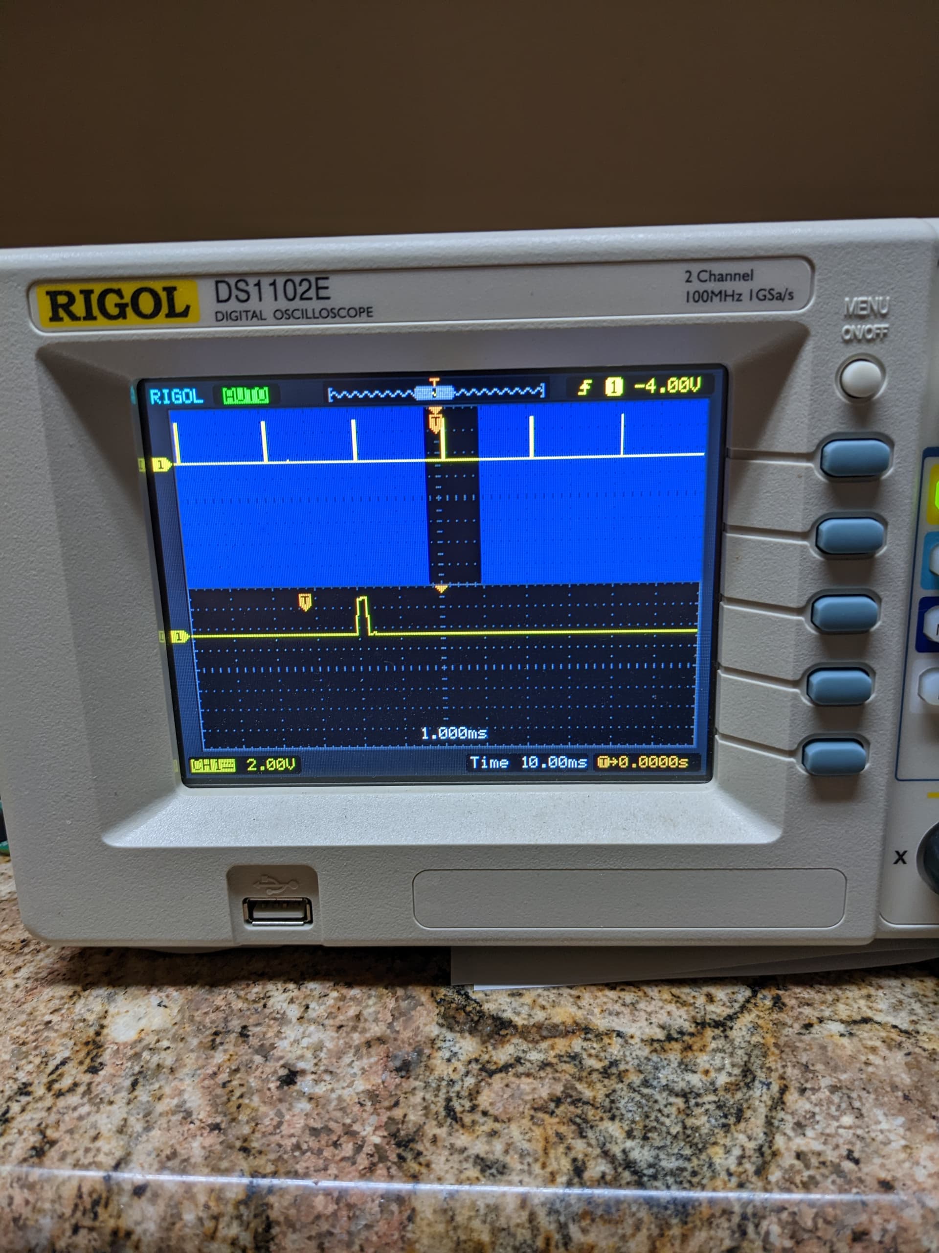
This is while the source was running and being attached to S16 on the servo headers, i.e. 15 in the source.
Second Photo:
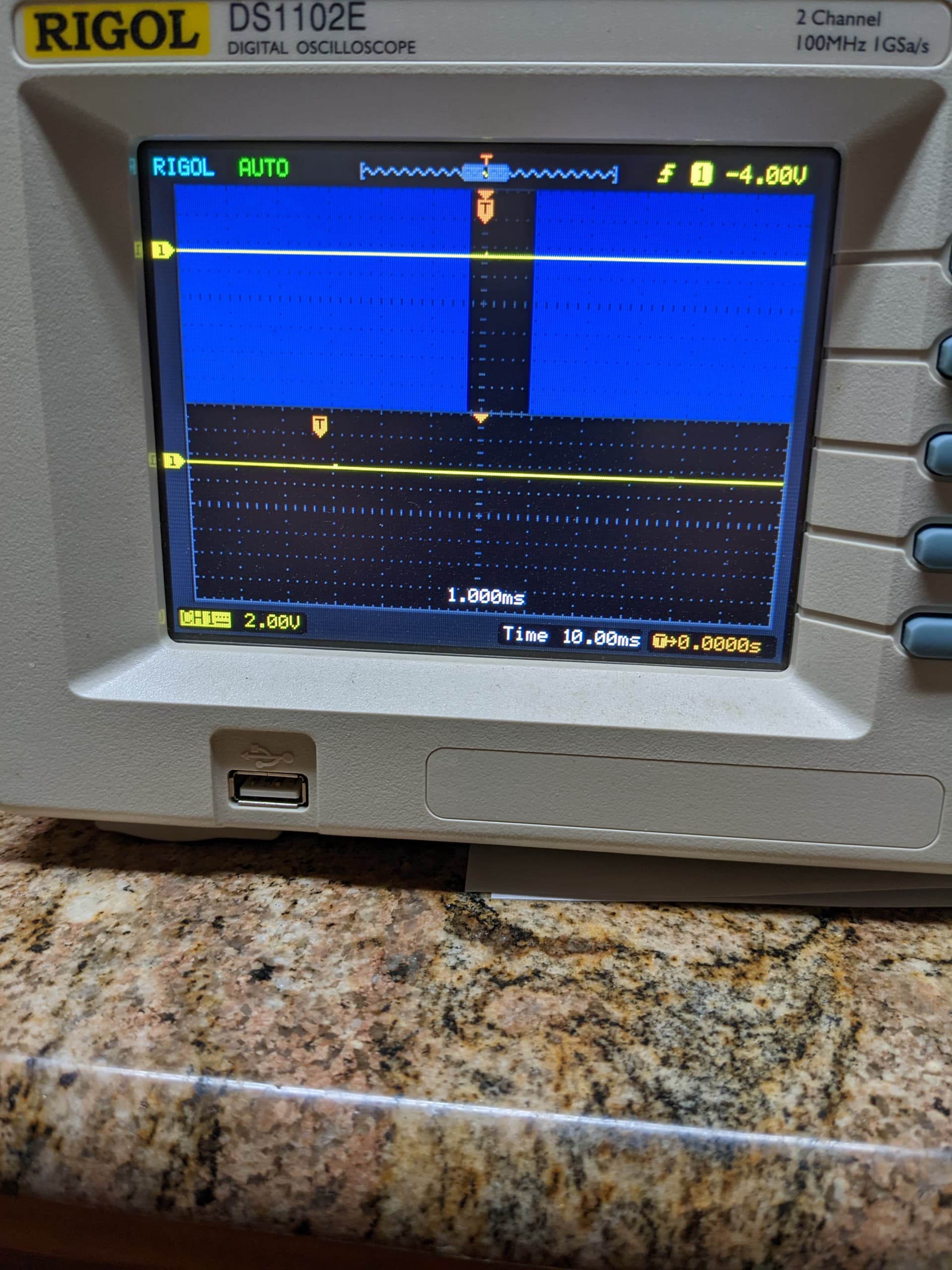
This photo is while attached but the source not being run on Servo 15/S16.
…
W/ the DMM and checking for Volts connected to GND and Signal on the Servo Headers, there is a 0.5mV when the source is off. When the source is on, there is a 41.7mV.
I am guessing here but that voltage should be at 3.3v maximum? Right? Anyway, this may indeed be an issue.
Please reply when convenient so I an understand more.
Also:
This may seem odd but how can I check if the GPIO68 on the BBB is being turned on/off when it is part of the ServoCape now? Could I just check on the BBB header pins?
Hi @silver2row
Yes if you have some solid core wire/breadboard jumps you can just stick them in the cape header pins. Safest way to check.
Anyway I can see a problem with the above.
So the values in the look good, But 61 is very wrong. For servo 15, this would be 66. Check your code where you are calculating the PWM register offset.
You should have something like (4 *servo)+6, where servo is 0 - 15.
At 61 you are partially writing to servo 13 and 14.
1 Like
Sir,
I am not sure you know what you are doing. I say that idea to say this idea. It works now!
The reasoning on why I said that short, curt statement was because of these ideas:
- W/out understanding, I am in the dark on why it works so far.
- I can move the servo…
Number 2. is not an issue. The servo moves!
Seth
P.S. Sir, I wonder something though currently. Is there a way to adjust the degree in which this servo moves? I mean…it moved to a point, supposedly 90 degrees via my input expression, where nothing else can be done to make it move back to its respective place.
If you need to see what was altered and changed, please let me know. I will be right back!
Sir,
@benedict.hewson , please see the below code on the small source written to handle the class and other functions.
#!/usr/bin/python3

from PCA_1 import *              # for the class and functions and source!
from time import sleep
from pathlib import Path
from smbus2 import SMBus

i2c_bus = SMBus("/dev/i2c-2")    # to call this into our class later which SMBus handles the file descriptor
'''
print ("{}".format(i2c_bus.read_byte_data(0x7f, 0)))
print ("{}".format(i2c_bus.read_byte_data(0x7f, 1)))
print ("{}".format(i2c_bus.read_byte_data(0x7f, 254)))
'''
pwm_controller = Pca9685(i2c_bus, 0x7f)    # a new call of the class handling the address and hex

set_pin = Path("/sys/class/gpio/gpio68/direction")    # handling pathlib fd output instance
set_pin.write_text("out")
set_pin = Path("/sys/class/gpio/gpio68/value")    # putting a value of "1" in value for gpio68 for turn it on
set_pin.write_text("1")

pwm_controller.set_pwm_frequency(50)    # Setting freq. from the function in our class
'''
print ("{}".format(i2c_bus.read_byte_data(0x7f, 0)))
print ("{}".format(i2c_bus.read_byte_data(0x7f, 1)))
print ("{}".format(i2c_bus.read_byte_data(0x7f, 254)))
'''
'''
pwm_controller.
pwm_controller.
pwm_controller.
'''

pwm_controller.get_pwm(15)    # trying an older routine function from the original source

pwm_controller.set_pwm(15, 50)    # another function in the class to handle servo number and freq.

def cort():
    try:
        while True:
            motion = int(input("Please enter a number from 0 to 180: "))    # input an int in "motion"
            if motion <= 180 and motion >= 0:    # use "and" or "or" to handle the motion if statement
                set_pin.write_text("0")    # Open our GPIO by setting "0" to value
                pwm_controller.get_pwm(15)    # functions from our class as 15, i.e. the value of our Servo
                pwm_controller.set_pwm(15, 50, motion)    # Servo number, freq, and our input
                pwm_controller.set_servo_angle(15, motion)    # Servo number and input
                sleep(2)
            else:    # else statement handling the Servo number, a freq, and our input w/ value == 0
                motion == 25
                set_pin.write_text("0")
                pwm_controller.set_servo_angle(15, 25, motion)
                sleep(2)
    except KeyboardInterrupt:    # Control-C Interrupt for handling python stoppage while testing source
        print (" Hello!")
        set_pin.write_text("1")    # cancels the source w/ a value entry of 1
cort()    # runs the source
And…
I am completely trying to understand more about the class and functions now (I am so slow at learning if it is not long and drawn out). Dang it.
Seth
P.S. So, that is testing to me so far. Now, I know the ServoCape works but in hindsight, I should have found a way to learn more about writing hex values to registers. I keep learning how to do it but I cannot do it yet. For one, I cannot fathom where 0xfff came from currently. Secondly, the important registers from before the class in PCA_1.py have not found their way into my understanding (somehow).
Also…
I can read about >> meanings in some form but the 8 is what in this line?
on_h = on >> 8
This fools me somehow.
Sir, sorry to contact you so many times here. I think I am getting it slowly but not quite. So, I will take some days, maybe two or three days, to learn more about altering source in the file w/ the class/functions/expressions.
There is something I am missing. Maybe reading some more source on this effort will be beneficial for me, you, and anyone learning like me on how to handle Servo(s) w/ the ServoCape.
Seth
P.S. If you reply one day out of the two or three days, okay. I will return service. If not, I will wait longer in case there are other things you would like to display or have me test.
Dang it. One thing to mention here or more things to mention here.
- The line to handle
offat the end, the lineset_pin.write_text("1"), for the GPIO68 OE pin brings the Servo to a particular spot. Do I know this degree? No, I do not. Is it0? I do not know. - When I run the listed source from above that supposedly handles the class and functions/expressions, I can only run the 45 degree once or 90 degree once and there is actually no way for me to know what degree the Servo is currently located.
Hello Sir,
I know this is more of a hardware concern, actual mechanics, but here:
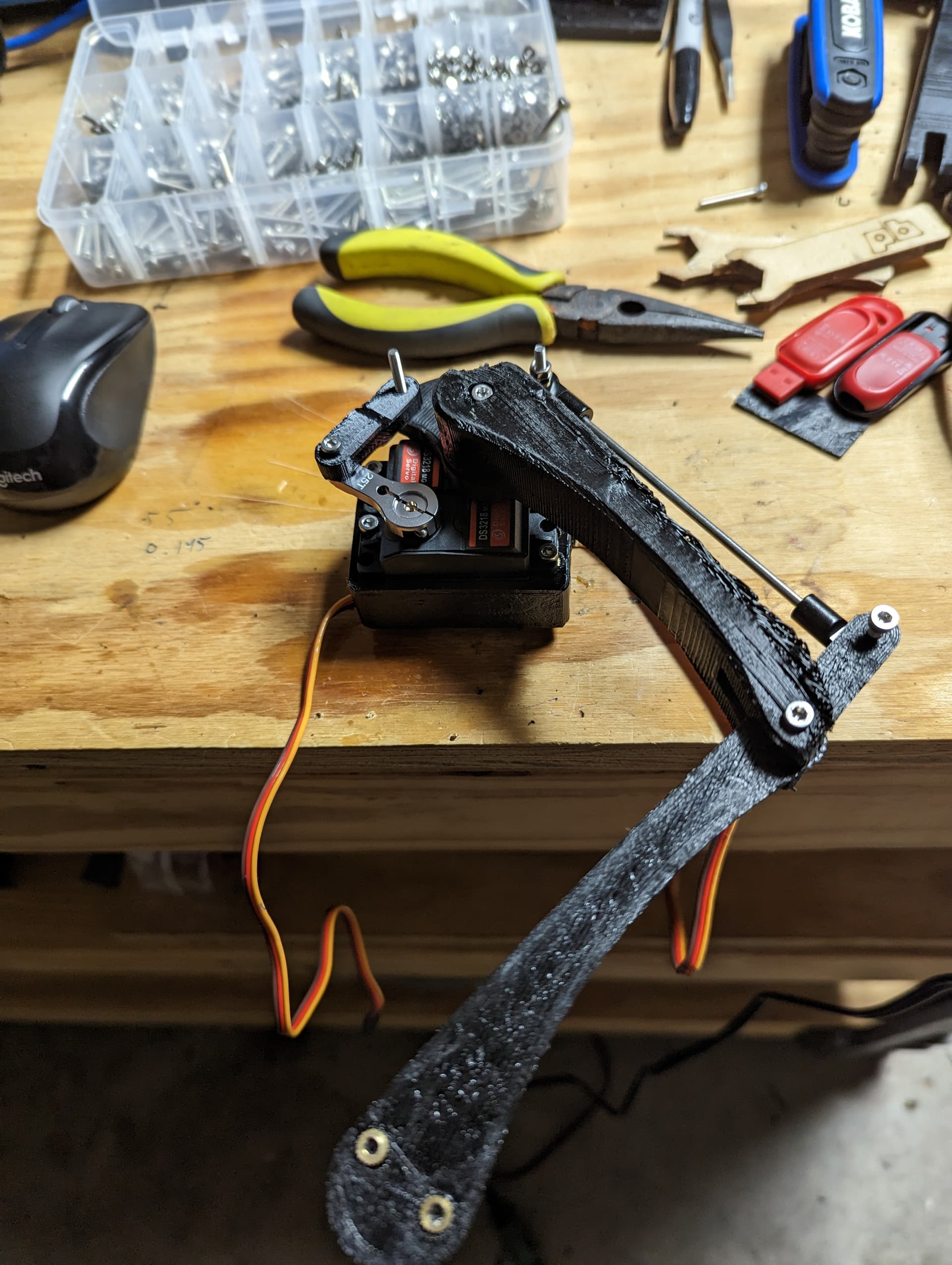
That is one leg of the quadruped. I know that the 3D Printing was not done by the BBB but a person that used to help build the RepliCape for the BBB.
Anyway, that legging is the last one to finish. So…phew. Done.
Now, I have to figure out how to handle 12 servos on this ServoCape to handle movement. Aw!
Seth
P.S. Here are the specifications on these motors:
Stall Torque (5V): 19 kg/cm (263.8oz/in)
Stall Torque (6.8V): 21.5 kg/cm (298.5 oz/in)
Dead band: 3μs
Speed : 0.16 sec/60°(5V) / 0.14 sec/60°(6.8V)
Operating Voltage: 4.8 ~ 6.8 DC Volts
Weight: 60 g (2.12 oz)
Motor Type: DC Motor
Working frequence: 1520μs / 333hz
Video coming soon on movement w/ the ServoCape.
There…it is the beginning so far. Oh! Before I take full credit, there were some people that helped like @benedict.hewson and this person for building the Open Source references for his build on the Quadruped: 3D Printed Robot Dog : 10 Steps (with Pictures) - Instructables