Hello,
This site: https://github.com/beagleboard/bb.org-overlays/tree/master/src/arm.
Is there one in particular .dtbo file that would be better suited for messing w/ the BBB and click boards?
Seth
P.S. I am asking to see if I need one of those .dtbo files for an overlay to use w/ the BBB and MikroBus Cape. If you are familiar w/ these overlays and the Cape in question, do not hesitate to ask or apply knowledge in this field.
Hello Again,
I meant the .dts files. Sorry.
Seth
All the files with this syntax:
BB-mBC*-CLICK.dts are tailored to:
BeagleBone Compatibility
+ mikroBus Cape: https://www.mikroe.com/beaglebone-mikrobus-cape
+ Stated CLICK..
Regards,
Hello,
Okay. I guess I will start to search through those .dts files to see if the click boards that are already written up are in my possession.
Thank you once more.
Seth
P.S. If you guys get around to XBee stuff, let a brother know. I have this nifty XBee click board for the Cape. Off to search through some books on how to connect XBee and BBB correctly (again)!
That CLICK board is a simple usart, it doesn't need an overlay, just
use config-pin and enable the uart..
Regards,
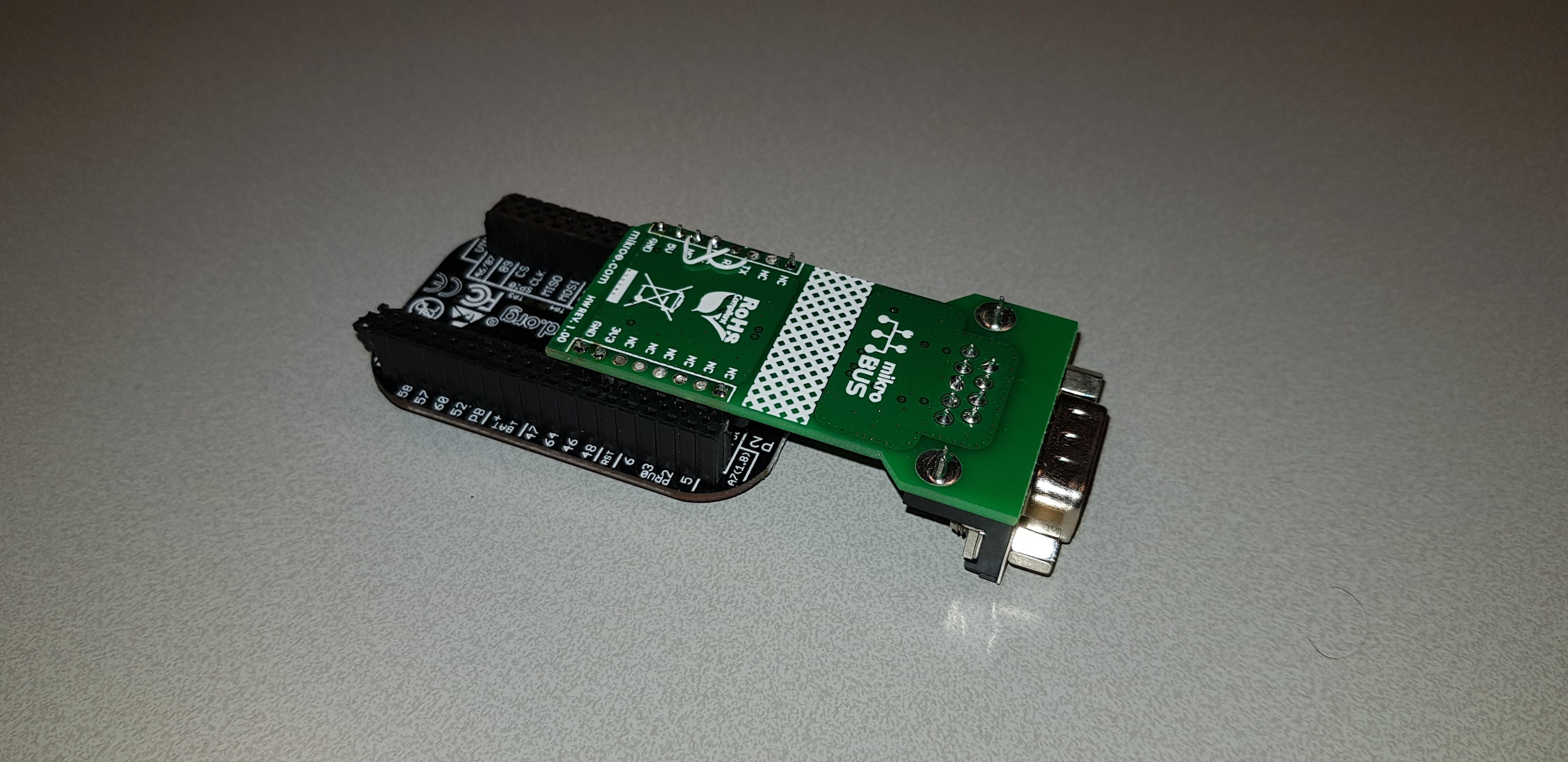
I just want to step into this discussion as I did have my share on the Click board usage.
I use them with the pocketbeagle, which is posted as being designed so that it is easy to integrate Click boards.
I found this to be not compeltely true:
Mechanical issues: The idea is to integrate at the processor side of the PCB, but the processor is so close to the holes that it is not possible to simply add a header to add the click board.
I decided to add the header on the other side and to adapt the click panel so that the pins stick to the other side.
If you are a bit handy it is feasible to do this, but you have to remain awake as you should never connect a “normal” Click board as it would result in feeding 5V in the 3.3V power of the click board.
Pin organisation issues: it might be a coincidence but the pins that are used to integrate the CAN RX/TX into the PB are only available for CAN after the boot proces, the processor uses them for some messaging while booting.
This is exactly something you don’t want: booting of the PB would result in corrupting the live CAN bus by sending rubbish messages in wrong bit rates, I had this issue and was puzzled why my canbus network went silent each time the PB booted.
So I moved the pins to another CANbus on the PB header (white wires)
I decided not to take the route of the overlay, just set up a script that defines the port configuration and other related actions (start my CANbus service) in the right order and enable this script as a service to be run at boot.
This was very convenient ans now I just have to maintain this script.
Gwen