Hi,
I would like to use GPIO with PB2 but I don’t understand the doc. There is an example on page 38:
to set the GPIO pin state to HIGH
debian@BeagleBone:~$ gpioset X Y=1
to set the GPIO pin state to LOW
debian@BeagleBone:~$ gpioset X Y=0
For Example:
±--------±---------+
| Pin | P1.03 |
+=========+==========+
| GPIO | 1 20 |
±--------±---------+
Use the commands below for controlling this pin (P1.03) where X = 1 and Y =␣
,→20
to set the GPIO pin state to HIGH
debian@BeagleBone:~$ gpioset 1 20=1
to set the GPIO pin state to LOW
debian@BeagleBone:~$ gpioset 1 20=0
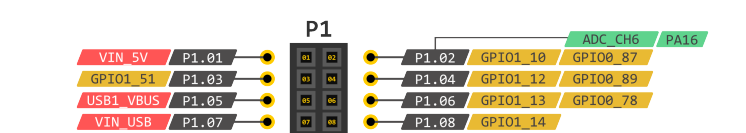
They talk about GPIO 1 20 for P1.03 but according to the pinout on page 36, P1.03 is GPIO1_51, am I wrong ?
Thx by advance for your help !