Hi there,
I’ve chosen the BeagleBone Black to build a horse feeding machine - and this is my first attempt on embedded systems.
I’m sitting in front of the reference manual looking at the expansion header P8 / P9 pinout to find out, which pins are the best for my application.
I need 8 digital out to drive DC motors via optocopler / mosfet
I need 8 digital in to get information via optocopler / reed contact
I need a serial input to get information from a TI-RFID System (TIRIS series 2000)
I need WIFI via USB
I would like to have the opportunity to connect a LCD touch and a camera
I don’t like shifting the IO’s, I don’t like to use the I2C or CAN bus.
Can somebody help me?
Thanks a lot
Kalle
PS:: If you understand German this is the page where I describe my system: http://www.hof-luettgesheide.de/index.php?article_id=263
USB is via the USB host connector as it does not appear on the expansion headers. You will need a USB hub as that is the best way to connect the camera as well.
You don’t need level shifting as long as all your voltages are 3.3V.
Serial requires the TX,RX so any of the serial ports on the headers can be used.
Gerald
Thanks for the hint with the USB - I had fear that USB and serial input are connected somehow. A powered hub is already bought.
So for Serial I’ll chose Pin 26 UART1 RXD and Pin 24 UART1_TXD.
The voltage at the IO pins will always be in correct level, because I’ll use optocouplers to protect the BBB.
But I’m confused, which pins will be the best for me. Nearly all pins have a 2nd or 3rd meaning and I’m not experienced enough to identify the ones I can use without causing trouble.
Can you just tell me 8 ins and 8 outs?
Thank You
Kalle
Processors today use pin muxing. The 2nd and 3rd are not meanings. They are the available options to be routed to those pins by setting a register in the processor. As long as you sue a function that is listed, you should have no problem. In other words, do not use a pin for UART1 that does not have UART1 as one of the listed options.
For IN use GPIO. For OUT use GPIO. DO not use the LCD pins because you said you wanted to support an undefined LCD.
UART1 is fine.
Gerald
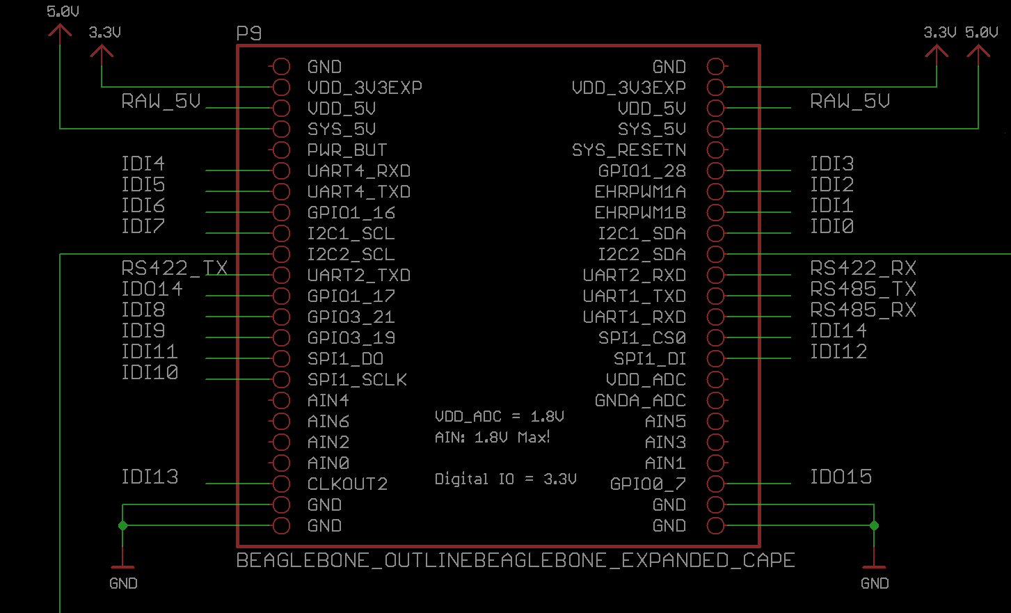
I would start with P9, that should give you 17 digital input/output pins to play with. P8 is mostly consumed by the LCD/HDMI and eMMC data lines. The directions (input vs output) are set in software, usually most pins are inputs on power up
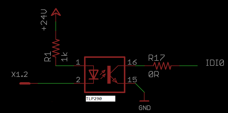
Here are a couple of schematics that I used for a cape… IDO are outputs and IDI are inputs
Louis

Louis, thanks for the schematics and the explanations.
It looks as if you already did the work I want to do. I want to create a stupid cape, to break out the in- and outputs.
Did you post your cape anywhere? Especially the eagle files?
Kalle