Is it possible to use a 74HC126 for I/O with my input commands controlling the output commands?
So, I can use input. I can use output. But, my commands cannot control the I/O in how I would like it controlled. It is basically because of some non-connected internals of the 74HC126.
I am learning slowly. So, bear with me on this one…
If you want to control input, here is the logic:
NC and COM

The Pull-Up Resistor:

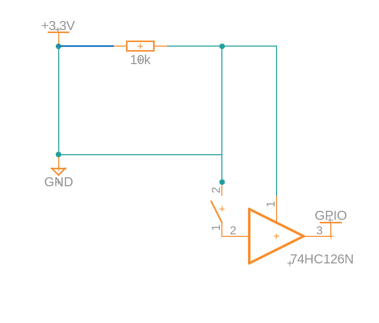
Connect a 10kΩ resistor between the 3.3V rail and the input
pin of the buffer (e.g., Pin 1A / Pin 2).

The Limit Switch:

Connect the NC (Normally Closed) terminal of your switch
to the same input pin (1A).

Connect the C (Common) terminal of the switch to GND.

The Buffer Output:

Connect the buffer's output pin (1Y / Pin 3) directly to
your BeagleY-AI GPIO pin.

Enable the Buffer:

Ensure the corresponding Output Enable pin (1OE / Pin 1) is
tied to 3.3V so the channel stays active.
I similarly use the output as the input but I cannot combine the logic for some reason with this 74HC126.
If you have any insider techniques for handling this specific chip and I/O, please jump on in.
Yes, the 74HC126 can buffer signals, but it won’t really “combine” input and output logic by itself. Each channel is just a tri-state buffer: A goes to Y when OE is high, and Y is disconnected when OE is low. There’s no internal feedback or decision-making between channels, so if you want an input command to control an output, the BeagleY-AI GPIO or some extra logic has to make that decision.
For your limit switch example, the pull-up + NC switch to GND is fine, then the Beagle reads that GPIO. Separately, another GPIO can drive an output buffer channel, LED, relay driver, etc. If you want hardware-only behavior, you’d likely need gates/latches or a different IC, not just the 74HC126. Also make sure everything is 3.3 V logic and don’t connect two outputs together unless one side is truly tri-stated.
With the 74HC126, I am unable to perform I/O logic per se. I think with some extra components, it is possible. This is where I am at a loss.
I understand so far that the OE and A and Y all mean something.
OE = Output Enable (when tied to GND, stall from the driver)
   = Output Enable (when tied to 3.3v, HIGH from the driver)

1A = input
1Y = output
The issue so far is that through source code, I cannot combine logic that is not there at all (74HC126).
Is there a way to trick the tri-state buffer * 4 into heeding the commands? For instance, would another component do just that idea? I guess this is where I am falling short now.
I can set the source code to understand the hardware. The limit switch (NC and COM) to input on the BeagleY-AI works with the source code. The two outputs, both GPIO, work with the source code.
The input and the outputs from the BeagleY-AI do not work so far together or in tandem. Although a bit funny, I understand the limitations of this buffer. Anyway, I think you understand. You understand that the 74HC126 is short sighted for I/O by itself since the GNDs and/or Vcc pins are not all connected by one OE pin.
Okay. I will try to wrangle up some schematic or diagram soon. @amf99 , Hey there…
What should I use to handle the schematic of the I/O from the BeagleY-AI? I mean to ask this question as it is more direct. What software should I choose to use for making the schematic?
Okay. I am learning about research over the Internet and learning about reading datasheets for the data needed to move forward:
@amf99 , I am editing this to test the beforehand circuit of putting the limit switch to Vcc instead of GND. Just to reiterate here, the limit switch was tied to Vcc via a 10k ohm resistor. I will test GND which is what I thought I did at first. Second chances * (100 * 10^3).
Update
This diagram/schematic of the listings and labeling has gone untested for now. Proceed with caution.
I am editing this time to clarify the statement of Vcc and GND changing with those connections being my tied to the wrong locations of the 74HC126. Hindsight is 10/10.
Update Again
So, I have a schematic unlike the garble from above:
With the 74HC126, I am unable to perform I/O logic per se. I think with some extra components, it is possible. This is where I am at a loss.
I understand so far that the OE and A and Y all mean something.
OE = Output Enable (when tied to GND, stall from the driver)
   = Output Enable (when tied to 3.3v, HIGH from the driver)

1A = input
1Y = output
The issue so far is that through source code, I cannot combine logic that is not there at all (74HC126).
Is there a way to trick the tri-state buffer * 4 into heeding the commands? For instance, would another component do just that idea? I guess this is where I am falling short now.
I can set the source code to understand the hardware. The limit switch (NC and COM) to input on the BeagleY-AI works with the source code. The two outputs, both GPIO, work with the source code.
The input and the outputs from the BeagleY-AI do not work so far together or in tandem. Although a bit funny, I understand the limitations of this buffer. Anyway, I think you understand. You understand that the 74HC126 is short sighted for I/O by itself since the GNDs and/or Vcc pins are not all connected by one OE pin.
You’re on the right track: the 74HC126 is not really “short sighted”, it’s just a very simple part. It only says: if OE is enabled, pass A to Y; if OE is disabled, disconnect Y. It will not look at your limit switch and decide what to do with another output unless you wire that logic externally or do it in software.
For what you describe, the usual choices are:
software logic: Beagle reads the limit switch GPIO, then enables/disables the output GPIOs
simple hardware logic: use gates such as AND/OR/NOT so the limit switch physically blocks the output signal
use OE as the “safety gate”: Beagle GPIO drives A, limit switch logic drives OE, so the buffer output is disabled when the switch trips
If the goal is “limit switch must stop the output no matter what the software does”, then don’t rely only on source code. Put the switch or some gate logic in the hardware path, possibly controlling OE. That is probably the missing piece here.
Thank you for replying again. Right. The limit switch (switch) should stop my motor from turning.
Then, the logic in the source code states: Once the limit switch is hit, move back 1600 steps.
I got it to work once or twice but the motor was severely hot. So, I know I was doing something incorrectly.
Thank you again for your insight. I removed all wires from the set up. I will attempt to put the wires back and the chip in place. This way, I can try to reiterate in practice what you know in hardware and source code logic.
I also noticed that some people use two switches for easier ways to handle source code logic. This would make my life easier but the breadboard only allows for so many I/O for now. So, thank you and I will test again soon.
My PWR and GND pins were not completely attached to the driver. The motor driver was only working because of ?. I do not even know why for now. I may never know.
The process you described almost works with my hardware and source code set up.
I think I am missing another component in the mixture of this testing phase.
Thank you.
I will try to get a schematic of the part and the GPIO and prototype done soon.
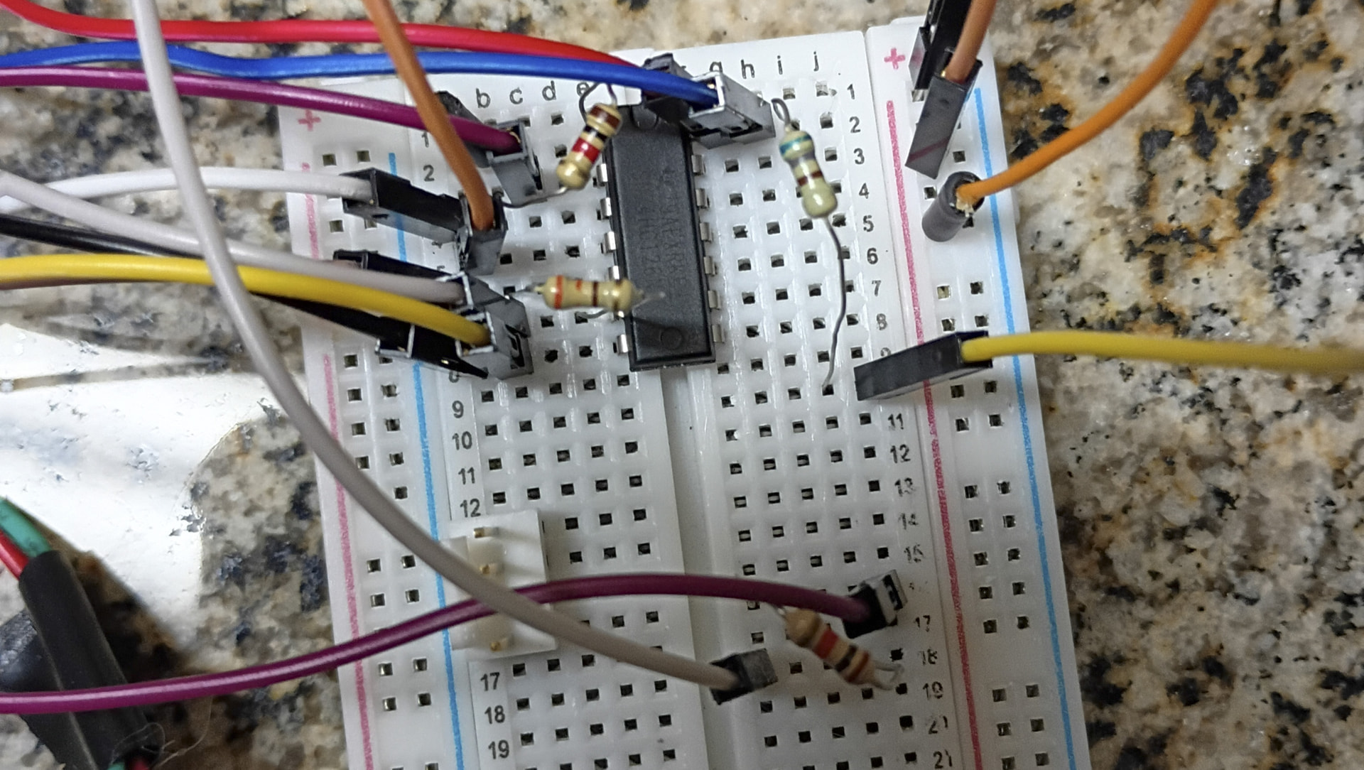
Now you can see why I was erratic on my postings. But yes and yes, that is the build.
Thank you for your words.
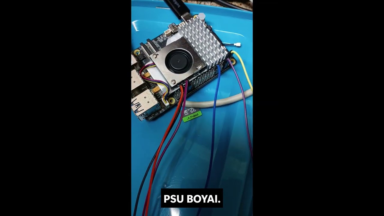
That is as good as my English gets these days (I am guessing). The automated speech to text editor is having a troublesome time with me. Ah well. Enjoy…the video is last (almost). BeagleY-AI!
9.2.2 Detailed Design Procedure

Add a decoupling capacitor from VCC to GND.
The capacitor needs to be placed physically close to the
device and electrically close to both the VCC and GND pins.
An example layout is shown in Section 11.

Ensure the capacitive load at the output is ≤ 70 pF.
This is not a hard limit, however it will ensure optimal performance.
This can be accomplished by providing short, appropriately sized traces
from the SN74HC126 to the receiving device.

// Ensure the resistive load at the output is larger than (VCC / IO(max)) Ω.

This will ensure that the maximum output current from the
Absolute Maximum Ratings is not violated.
Most CMOS inputs have a resistive load measured
in megaohms; much larger than the minimum calculated above.

Thermal issues are rarely a concern for logic gates, however the
power consumption and thermal increase can be calculated
using the steps provided in the application report, CMOS Power Consumption
and Cpd Calculation
The line marked with // is what I am discussing now:
(Vcc / Io (MAX)) ohm means exactly what to me?
Does this mean:
(3.3v / 35 mA (MAX)) ohm where who knows what MAX means and how ohm got in the mix, no clue.
Io could be the actual measured mA while MAX is +/- 35 mA like the datasheet states.
I am still having no clue about ohm in this context.
Update
Since the last post, I have grounded all the floating pins that had no I/O attachments.
I’m not trying to dissuade you or belittle your endevour, but 12 years?
Points for tenacity, I guess…
Sometimes it’s ok to accept that something is out of ones league and
get some help. If I were you, I’m pretty sure I would have gotten a
turn-key motor/driver solution instead; in this case I’m like you, I don’t
know the first thing about motors, and just like with my car, I take it
to the Garage if something’s wrong and let them deal with it, while
I can spend my time tinkering with something I do know something about…
I am editing this because you typed 2 cents instead of two cents. @lranders , what in the world makes you comment on some person’s slow motion abilities? I mean…
Are you pointing out that you are smarter than silver2row and this fellow named Seth? I really do not get it. You could easily write me off and tell me to eat garbage and die but instead you are being collective at times while hateful at other times.
Did you manage to read any of what I wrote instead of whatever bit
made you jump off the deep end like that?
All I did was reflect on my own sadly finite life and conclude
that I at least would not spend 12 years fighting a motor.
I also said that there’s no shame in conceding defeat if ones time
can be better spent taking a shortcut by using a pre-existing solution.
Case and point: I don’t make Rocket-ships; I’m not cleaver enough to do so.
Furthermore, I feel no shame admitting that to myself or anybody else…
Heck, even NASA doesn’t; they focus their efforts on what they’re really good at:
Orbital Mechanics and Flight Trajectories. You don’t see them build Rockets either.
At no point did I say that I am smarter than you,
but I do try to be a bit more judicious with what little time I’ve been given.
In closing, I really don’t know why you’re describing yourself as two different persons.
Ofc., I can’t know for sure, but you sure do seem to work on exactly the
same problems and ask exactly the same questions…
I understand. I get out-of-control at times. I apologize. I know you are willing to help at times. I should know how to keep my mouth closed or fingers away from the keyboard. Either way, I am working now on the software to show a slight sign of progress…
So, right now I am currently trying to show the stability of source code and hardware with the GPIO peripheral of the BeagleY-AI.
Nothing too out of the ordinary but I would like to learn more. I remember you saying some 74LVC chips may provide a simpler approach to my motor fun.
I ordered a couple.
Just you wait.
I understand what you were typing and it shoved my boat. I apologize to you now. I should have blown it off and not thought about it too deeply.
Anyway, thank you for helping me and applying additional data when needed.
In the future, I will just admit to myself that you are not like me and we may scuffle in words from time to time but in the end, I win. Ha.
Seth
P.S. Wait for the 74LVC approach next. I see that the 74LVC chips have an all enable pin and in positive logic. Those inverters were getting to me.
Update
and if anyone should declare that the 74HC126 chips are unknown to some CAD/CAM programs, look to Autodesk Fusion. They actually have the 74HC126 style of chip for use while setting up diagrams/schematics. It should be easy for some of you who know the lay of the land well. I am still learning how to handle schematics and layouts well.
Hey sir, I got it! Simple logic and 1,000,000 tasks beat me simplistically. The driver, the BeagleY-AI, and the 74HC126 all work like a charm. break time!
Motor heating is a separate red flag from the limit logic, usually points at the driver/current side rather than the 74HC126. Two endstops do make the motion state a lot less awkward once the wiring is sorted.
Yeppers. I noticed that some builds have two switches instead of one. This makes the linear moves have absolute stopping points instead of guessing stopping points.
I figured out the issue with the driver and motor also. I was using too much amperage in the driver.