[AntMiner] from Blackminer FPGA constant blinking red light

I’m very much a newbie to this, I have attempted to update my firmware on my Beaglebone Black that is connected to a Blackminer F2 FPGA. I can not see its IP at all on my network and I have blinking red light after it boots up.

ipconfig/all and arp -a do not show anything

the blinking red light happens after blue LED’s go out, green lights momentarily and then red blinks steady

the ethernet lights stay frozen on.

I have a fresh Micro SD Card I’m going to try and load Debian onto it, but doubt that will resolve this, and I am not well versed with Linux, but could muddle through it.

How the heck can I reset this using a hardware reset?

If I were to replace this, in theory I could use a newer BeagleBone board with wi-fi to run my device if loaded with proper firmware from Blackminer correct? I don’t want to order the specific board from China preferrably lol.

Thank you!

This is not an official BeagleBone Black, even though it has the words, “BeagleBone Black v2.3” on the Silkscreen…

It is an un-licensed clone produced by Antminer for their product line…

We (BeagleBoard.org) do not have access to their pcb changes, from other customers discussions, we have found they utilize onboard NAND with different sysboots pins, which we never utilized…

For any support on this product contact Antminer.

Regards,

Regardless of this, has anyone in the community opted to create a schematic of this, or tinker with it?

I’m assuming unlicensed clone means another foreign nation using trade names incorrectly…

What would one do for a proper BeagleBoard in order to hard reset it?

At this point, I’m okay with giving whatever a shot. I can’t connect to it, so I’m assuming it’s the part of the board associated with networking (no IP is shown at all). I’m likely stuck ordering a new BeagleBone and Blackminer (not Antminer, but they use similar boards) control board.

Hi, there
I have like 7 pcs of those (2 or 3 versions from Antminer S5) and recently start tinkering with them, it’s a shame to watch how they rot in a box :slight_smile:
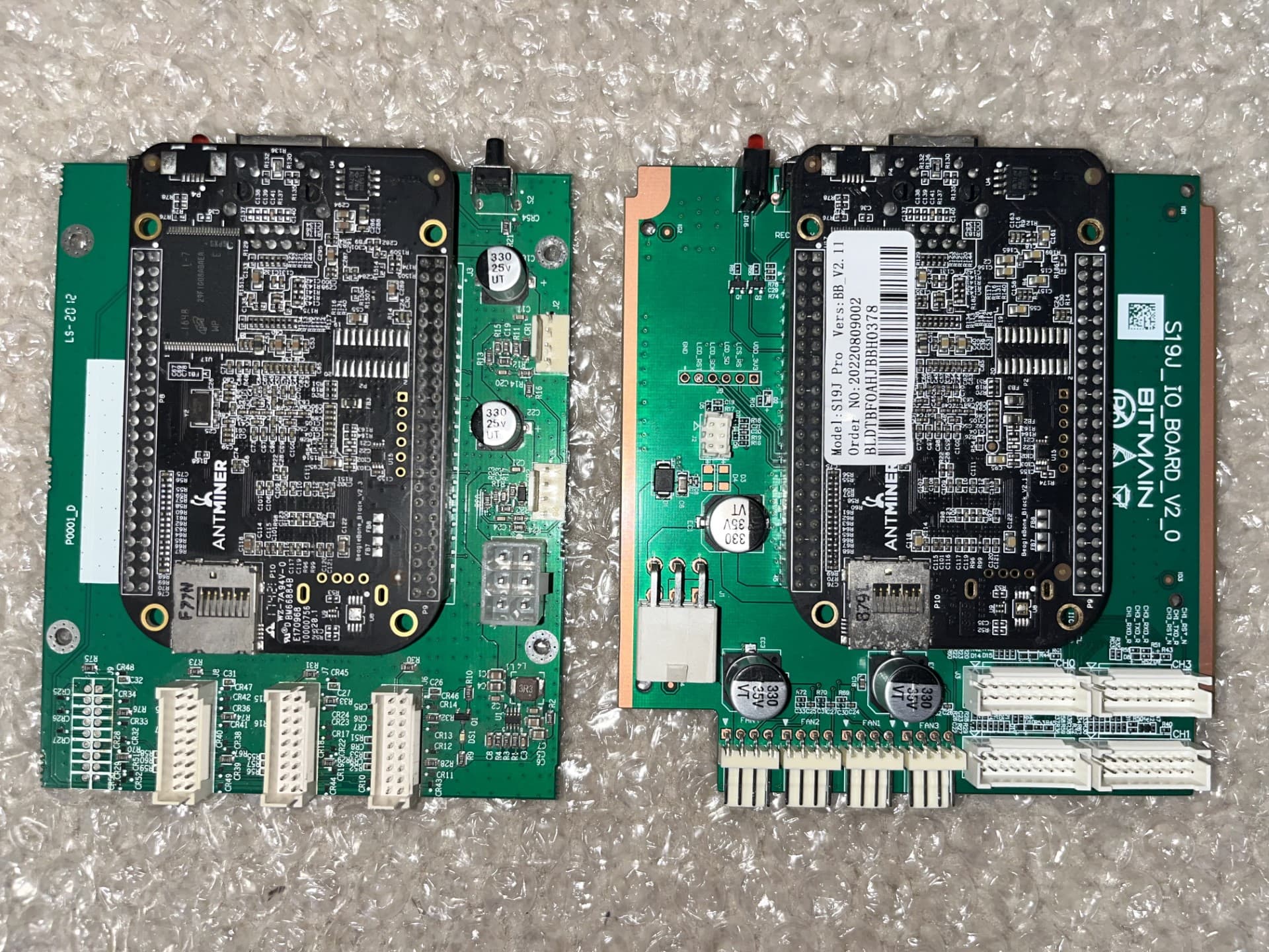
Most probably your board is very similar…
My have following model: S5/Bb/v1.5
it’s based on TI AM5532 CPU (don’t have PRU cores)
and working from 256Mb (2Gbit) NAND chip “MT29F2G08ABAEA WP IT E”
DRAM: 512
My main goal is to create and load latest images like Bullseye from uSD
I think this kind of boards still very usable for many things like driving 3D printer with Klipper, do RS-485 MQTT bridge, etc …

While I was playing with one of them I did try to update u-boot to latest version because of old u-boot didn’t want to accept latest images, in the end I get corrupted NAND state and board didn’t show any signs of life only red led was glowing (not blinking).
This started a chain of documentation digging, soldering, etc … - just for fun :slight_smile:

Short story - I did manage to bring back life to it and did accumulate some knowledge about software and hardware.

First what you need to do is to solder Serial headers (J1) and hook-up serial cable to them (3 pins (gnd,rx,tx), pinout is same as for standard BeagleBone black, then connect with serial connection (baud 115200).
When terminal is ready power-up the board and see what it will show you.

If NAND is in good state you will see u-boot and loading sequence (and why it’s failing) and will be able to interact with it, also most probably in this state you still can boot from uSD images.

If NAND is corrupted - serial will be silent, only some single character will appear when you are disconnecting power (or it will be completely silent), just be sure you didn’t mismatch RX with TX pin :slight_smile:

If NAND is corrupted - most probably uSD card with images will not help because the default boot order for that board is hardwired for following order: NAND NANDI2C MMC0 UART0
(SYSBOOT[4:0] = 10011h)
Shorting boot button headers will not help you in this state because it should drive SYSBOOT[2] to low, but it’s already in this state.

I did manage to switch boot order to following: MMC0 SPI0 UART0 USB0
(SYSBOOT[4:0] = 10111h)
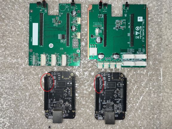
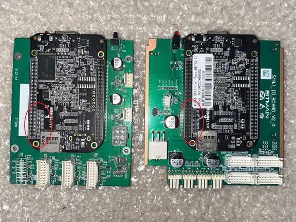
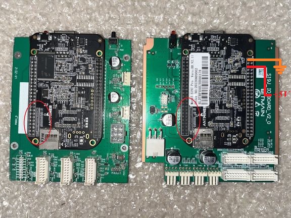
By moving 100K smd resistor from R93 to R68 - this switched SYSBOOT[2] to High state, and now shorting “Boot” button can control boot order - if shorted I get original order, if not I get new boot order.

As an option maybe you can try to pullup SYSBOOT[2] without moving of smd resistor by shorting pin P8_43 with +3.3v (Pin P9_3) thru 1k or 0.1k resistor - but i didn’t try that.

But again it was old AntMiner S5 BeagleBone - i’m not sure what you have, before doing any stuff - send hi-def pictures of your board, especially rows of resistors around P8 from both sides of board - usually they are controlling boot order - i can visually compare it with mine.
If you will get some output from Serial console - send it - maybe I will be able to drive you in right direction.

This is a response more in line with what I was looking for.

I’ll take pictures as I have 2 boards, one is a new one from an S19J Pro with firmware I can not remove (not braiins OS) using an SD card to flash it.

It’s been a while since I have soldered components this small…a long while.

Hi, photos are pretty coarse, do closeup on this areas
thumbnail_IMG_4610
thumbnail_IMG_4609

Most probably you can try to power-up your BB board without additional mining control board, just supply +5v to these, pins.
If you want to re-check this possibility - you can measure voltage difference on these pins when you are running it from mining control board, you should see there +5v.

Original BeagleBone Black also can be powered this way,
pins P9_01 + P9_02 - are GND,
pins P9_05 + P9_06 - are +5v
pin P9_09 to Gnd for start-Up (same as power button)
but in antminer board it will startup after supplying power (without power button)

thumbnail_IMG_4609

Just noticed that I made an error in CPU model description, it should be AM3352

I did compile together all my finding about Antminer boards and place them here:

There I explain everything about board, issues, images, workarounds, etc …