Hi Jason,
while doing a HW schematics I noticed a discrepancy in on the Beaglebone Black Schematics and the DDR3 chip
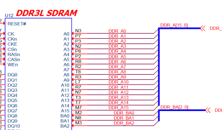
On Page 7 you have on the DDR3L 4 GB RAM chip a A0 – A15 bus wiring to the AM3558 chip BUT
[cid:image001.png@01D618AC.292C29D0]
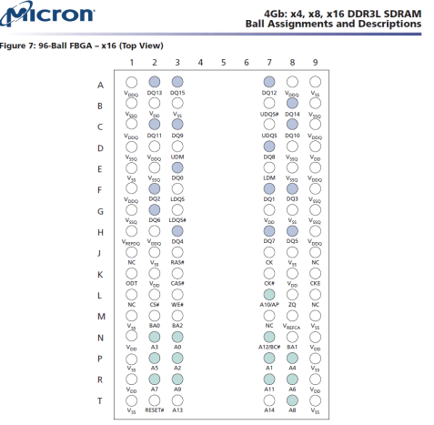
But the 2 MICRON Chips MT41K256M16HA-125:E and MT41K256M16TW-107:P say A15 / PIN M7 is not Connected.
[cid:image002.png@01D618AC.292C29D0]
I this an error in the drawing or is A15 for the alternative Kingston Chips you have in your BB Black Parts List.
Strangely you do not get any detailed manual with pin Lazyout for the Kingston chips ??
Can we wire only A0 to A14 and USE onle Micron Chips ??
Please comment.
Best Regards
Bernhard Panait
Bernhard.Panait@globalinvacom.com<mailto:Bernhard.Panait@globalinvacom.com>
Global Invacom Manufacturing Ltd. (APEXSAT)
[GI Logo]
This email and any files transmitted with it are confidential and intended solely for the use of the individual or entity to whom they are addressed. If you have received this email in error please notify the system manager itcontact@globalinvacom.com<mailto:itcontact@globalinvacom.com>. This message contains confidential information and is intended only for the individual named. If you are not the named addressee you should not disseminate, distribute or copy this e-mail. Please notify the sender immediately by e-mail if you have received this e-mail by mistake and delete this e-mail from your system. If you are not the intended recipient you are notified that disclosing, copying, distributing or taking any action in reliance on the contents of this information is strictly prohibited
Privacy - maintaining the security of your data is a priority at Global Invacom, and we are committed to respecting your privacy rights. We pledge to handle your data fairly and legally at all times. Global Invacom is also dedicated to being transparent about what data we collect about you and how we use it. Further information can be found at the following link; http://www.globalinvacom.com/privacy


Hi Jason,
while doing a HW schematics I noticed a discrepancy in on the Beaglebone Black Schematics and the DDR3 chip
On Page 7 you have on the DDR3L 4 GB RAM chip a A0 – A15 bus wiring to the AM3558 chip BUT

But the 2 MICRON Chips MT41K256M16HA-125:E and MT41K256M16TW-107:P say A15 / PIN M7 is not Connected.

I this an error in the drawing or is A15 for the alternative Kingston Chips you have in your BB Black Parts List.
Strangely you do not get any detailed manual with pin Lazyout for the Kingston chips ??
Can we wire only A0 to A14 and USE onle Micron Chips ??
The Kingston chips use the same pinout, which is specified by JEDEC (“JEDEC Standard No. 79-3C” should do the trick). For 256Mx16 (512MB, 4Gb) devices, A15 isn’t used.
It is really just as simple as the layout supports 512Mx16 (1GB, 8Gb) devices, but aren’t populated that way. If you’ll never use 1GB devices, you don’t need to route A15.

Hi Jason,
while doing a HW schematics I noticed a discrepancy in on the Beaglebone Black Schematics and the DDR3 chip
On Page 7 you have on the DDR3L 4 GB RAM chip a A0 – A15 bus wiring to the AM3558 chip BUT

But the 2 MICRON Chips MT41K256M16HA-125:E and MT41K256M16TW-107:P say A15 / PIN M7 is not Connected.

I this an error in the drawing or is A15 for the alternative Kingston Chips you have in your BB Black Parts List.
Strangely you do not get any detailed manual with pin Lazyout for the Kingston chips ??
Can we wire only A0 to A14 and USE onle Micron Chips ??
The Kingston chips use the same pinout, which is specified by JEDEC (“JEDEC Standard No. 79-3C” should do the trick). For 256Mx16 (512MB, 4Gb) devices, A15 isn’t used.
It is really just as simple as the layout supports 512Mx16 (1GB, 8Gb) devices, but aren’t populated that way. If you’ll never use 1GB devices, you don’t need to route A15.
I forgot to mention to read the DDR routing guides in http://www.ti.com/lit/ds/symlink/am3358.pdf.

Hi Jason,
I have 2 more questions
I see on the Beaglebone schematics several resistors and capacitors with DNI label which I assume is DO NOT INSTALL. This means the resistor and capacitors are not to be installed but the wire/wiring still to be made. PLEASE CONFIRM.
Which leads us to the second question:
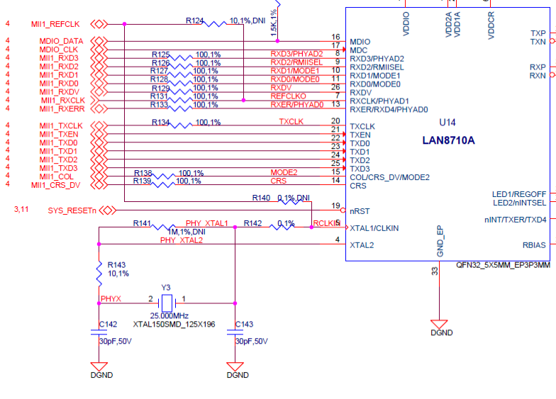
On the LAN Chip Page 9 we have 2 split wire going via R124 and R140 DNI to the AM3358 MII1_REFCLK(see below)
I do not have a MII1_REFCLK pin as it is used for other purposes.

As already the “”main” wires from Pin 7 go to MII_RXCLK & Pin 5 go to a Crystal Oscillator I assume the R140 wire and the R124 wires are only Backup clocks and do not need to be attached completely (wire and Resistor) Please confirm.
Best Regards
Bernhard Panait
Bernhard.Panait@globalinvacom.com
Global Invacom Manufacturing Ltd. (APEXSAT)


