BB-AI64 GPIO basics

Hello,

I am trying to toggle GPIO outputs with my BB-AI64. I have the latest install from ARM64 - Debian 11.x (Bullseye) - Monthly Snapshots - 2023-09-02 and got a wifi module up and running (AX210).

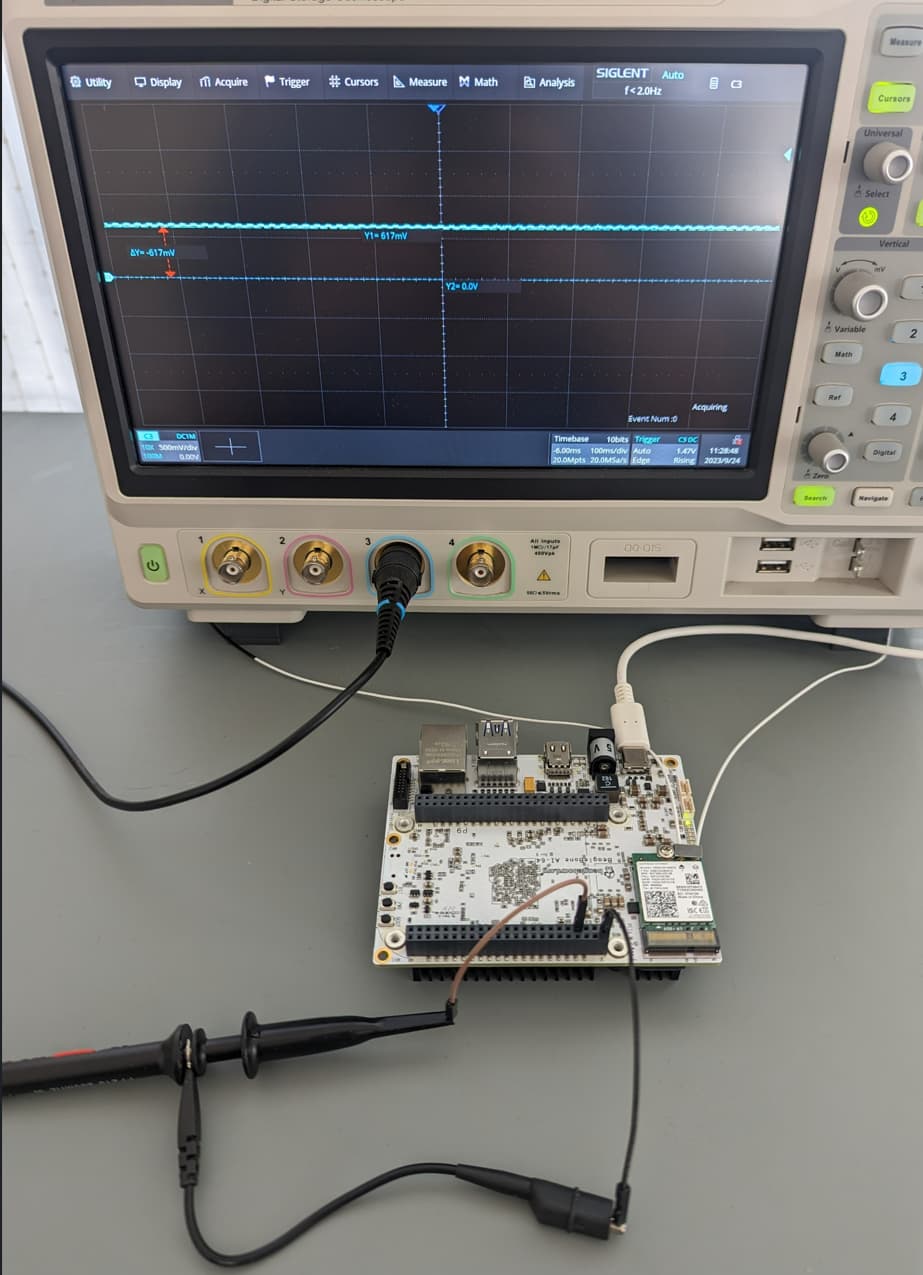
With no mods to the system, apart from the wpa_supplicant for the wifi, I am trying to do a basic GPIO output control. So far, when observing the line on the scope (probe into P8), all I get is 750mV, so High-Z on the line. I tried multiple pins on P8 and P9 and always get the same result.

In the following two attempts , I probe pin 7 of connector P8 and never see any activity, always 750mV.

Method 1: from the documentation at:
https://docs.beagleboard.io/latest/boards/beaglebone/ai-64/ch07.html

debian@BeagleBone-AI64:~$ gpioinfo | grep P8_07
        line  15:      "P8_07"       unused   input  active-high
debian@BeagleBone-AI64:~$ gpiodetect
gpiochip0 [42110000.gpio] (84 lines)
gpiochip1 [600000.gpio] (128 lines)
gpiochip2 [601000.gpio] (36 lines)
debian@BeagleBone-AI64:~$ gpiofind P8_07
gpiochip1 15
debian@BeagleBone-AI64:~$ gpioset 1 15=1
debian@BeagleBone-AI64:~$ gpioset --mode=wait 1 15=1
^C
debian@BeagleBone-AI64:~$

->> scope trace for P8 pin 7 always stays Hi-Z

debian@BeagleBone-AI64:~$ gpioinfo | grep P8_07
        line  15:      "P8_07"       unused  output  active-high
debian@BeagleBone-AI64:~$

Method 2: from the post AI-64 - GPIO sysfs

debian@BeagleBone-AI64:~$ gpiodetect
gpiochip0 [42110000.gpio] (84 lines)
gpiochip1 [600000.gpio] (128 lines)
gpiochip2 [601000.gpio] (36 lines)
debian@BeagleBone-AI64:~$ gpiofind P8_07
gpiochip1 15
debian@BeagleBone-AI64:~$ ls -ltr /sys/class/gpio/gpiochip*
lrwxrwxrwx 1 root root 0 Jan  1  1970 /sys/class/gpio/gpiochip428 -> ../../devices/platform/bus@100000/bus@100000:bus@28380000/42110000.gpio/gpio/gpiochip428
lrwxrwxrwx 1 root root 0 Jan  1  1970 /sys/class/gpio/gpiochip300 -> ../../devices/platform/bus@100000/600000.gpio/gpio/gpiochip300
lrwxrwxrwx 1 root root 0 Jan  1  1970 /sys/class/gpio/gpiochip264 -> ../../devices/platform/bus@100000/601000.gpio/gpio/gpiochip264
debian@BeagleBone-AI64:~$ echo 315 > /sys/class/gpio/export
debian@BeagleBone-AI64:~$ ls /sys/class/gpio/
export  gpio315  gpiochip264  gpiochip300  gpiochip428  unexport
debian@BeagleBone-AI64:~$ echo out > /sys/class/gpio/gpio315/direction
debian@BeagleBone-AI64:~$ echo 1 > /sys/class/gpio/gpio315/value
debian@BeagleBone-AI64:~$

->> scope trace for P8 pin 7 always stays Hi-Z

I’m thinking I am missing a step to enable the outputs? Any suggestion or pointer to the right documentation would be appreciated!

Thank you

Hi Xtof,

I am able to toggle the pin voltage of P8_07.
Can you able to do below steps and check again like installing libgpiod library.
git clone GitHub - brgl/libgpiod: NOTE - this project is now hosted at kernel.org and the development happens on the linux-gpio mailing list.
gpioset 1 15=1 ---->3.3v
gpioset 1 15=0 ---->0.0V

Regards
Manan Jarsania

Thanks, Manan, for trying it out and getting back to me! I thought it should work… strange.

I had libgpiod installed but I still re-built it from the git repo and same thing: the commands execute but the scope trace stays around 600mV to 700mV like it’s a floating input. But as shown in my post above, gpioinfo returns “output” for that pin after gpioset is run.

Here’s a picture of my simple “Hello world” setup:

Any suggestion would be great!

Thanks.

Hi xtof,

Actually I have 2 AI-64 board. In 1 board I have checked and replied.
But when I checked on another board. Same issue I faced.

I don’t know what to do.
At least we can comment on the discord channel as well.
please make a login and comment there. I will also ask same thing.

BeagleBoard.org.

Regards
Manan

1 Like

Well, I somewhat feel better that it’s not just me! I want to try a few things first, maybe someone will have ideas by then, but if not, that’s a good idea, we can take it over to Discord then.
Thanks!

GPIO is not working with the newer firmware. I found that bbai64-emmc-flasher-debian-11.6-minimal-arm64-2023-04-06-4gb.img.xz was the latest to still have working GPIO. You can grab it at Index of /rootfs/bb.org/testing/2023-04-06/bullseye-minimal-arm64.

Burn that image to a microSD using rufus or something. Plug that microSD in, power on your bbai64 while holding down the boot button. Keep holding that button down until the LEDs start going crazy, will take about 10 seconds. Next you’ll have to wait about 5 - 10 minutes. After the LEDs stop going crazy unplug the board, remove the microSD, and then start the board back up.

Somewhere along the line, the GPIO stuff in the devicetree went missing and the GPIOs stopped working.

	/* Dummy driver to request setup for cape header pins */
	cape_header: pinmux_dummy {
		compatible = "gpio-leds";
		pinctrl-names = "default";
		pinctrl-0 = <
			&P8_03_default_pin
			&P8_04_default_pin
			&P8_05_default_pin
			&P8_06_default_pin
			&P8_07_default_pin
			&P8_08_default_pin
			&P8_09_default_pin
			&P8_10_default_pin
			&P8_11_default_pin
			&P8_12_default_pin
			&P8_13_default_pin
			&P8_14_default_pin
			&P8_15_default_pin
			&P8_16_default_pin
			&P8_17_default_pin
			&P8_18_default_pin
			&P8_19_default_pin
			&P8_20_default_pin
			&P8_21_default_pin
			&P8_22_default_pin
			&P8_23_default_pin
			&P8_24_default_pin
			&P8_25_default_pin
			&P8_26_default_pin
			&P8_27_default_pin
			&P8_28_default_pin
			&P8_29_default_pin
			&P8_30_default_pin
			&P8_31_default_pin
			&P8_32_default_pin
			&P8_33_default_pin
			&P8_34_default_pin
			&P8_35_default_pin
			&P8_36_default_pin
			&P8_37_default_pin
			&P8_38_default_pin
			&P8_39_default_pin
			&P8_40_default_pin
			&P8_41_default_pin
			&P8_42_default_pin
			&P8_43_default_pin
			&P8_44_default_pin
			&P8_45_default_pin
			&P8_46_default_pin
			&P9_11_default_pin
			&P9_12_default_pin
			&P9_13_default_pin
			&P9_14_default_pin
			&P9_15_default_pin
			&P9_16_default_pin
			&P9_17_default_pin
			&P9_18_default_pin
			&P9_19_default_pin
			&P9_20_default_pin
			&P9_21_default_pin
			&P9_22_default_pin
			&P9_23_default_pin
			&P9_24_default_pin
			&P9_25_default_pin
			&P9_26_default_pin
			&P9_27_default_pin
			&P9_28_default_pin
			&P9_29_default_pin
			&P9_30_default_pin
			&P9_31_default_pin
			&P9_33_default_pin
			&P9_35_default_pin
			&P9_36_default_pin
			&P9_37_default_pin
			&P9_38_default_pin
			&P9_39_default_pin
			&P9_40_default_pin
			&P9_41_default_pin
			&P9_42_default_pin
		>;
	};

The contents of the k3-j721e-beagleboneai64-bone-buses.dtsi file were different between the previous and current versions.

When I applied the above code to the dtsi and created the dtb file, the GPIOs worked fine.

5 Likes

To document the steps for non-software experts who like myself might have a hard time figuring out where the files that need edited are hiding and how to apply the changes (and if applicable to gather feedback on how to do it better), here is what I ended up doing to get it working on a clean install, based on the great feedback from all who responded to this thread:

  1. Flash recent image: bbai64-emmc-flasher-debian-11.8-xfce-arm64-2024-01-11-10gb.img.xz found at https://rcn-ee.com/rootfs/debian-arm64-11-bullseye-xfce-v5.10-ti/2024-01-11/

  2. Set up network (I use a wifi card so I set up my wifi ssid/password in /etc/wpa_supplicant/wpa_supplicant-wlan0.conf) so you can transfer files to the BBAI64.

  3. Grab k3-j721e-beagleboneai64-bone-buses.dtsi from a pre-March 2023 image that includes the missing section documented above:
    k3-j721e-beagleboneai64-bone-buses.dtsi (44.6 KB)
    And use it to replace the one already in /opt/source/dtb-5.10-ti/src/arm64

  4. In directory /opt/source/dtb-5.10-ti/ run:

sudo make clean
sudo make
sudo make install_arm64

  1. reboot

I guess the existing /opt/source/dtb-5.10-ti/src/arm64/k3-j721e-beagleboneai64-bone-buses.dtsi could be edited to add the missing section but it’s a large file so it was easier to simply replace it.

Thanks again to all who helped!

3 Likes

It turns out GPIO is disabled by default with intent. With all GPIOs enabled by default, overlays were getting stomped on. The current correct thing to do is to make a custom overlay for the GPIO pins you want to enable.

Link to chat with @RobertCNelson on this: Discord #beaglebone-ai-64
Little bit of info on making a custom GPIO overlay: BeagleBone cape interface spec — BeagleBoard Documentation

3 Likes

Hi all.
I spent hours, but didn’t manage to make gpio work. I need one input pin, which i can read in C program. As i understand, the method /sys/class/gpio/… is deprecated and only one option - to build custom dto. I have updated BBORG_RELAY-00A2.dts with block:
// key1
&bone_key_P9_15 {
status = “okay”;
label = “key1”;
default-state = “keep”;
};
compiled and updated boot config. I expected that ‘key1’ will appear somewhere in /sys and I can read it state. But nothing happened, only one effect i achieved - /sys/firmware/devicetree/base/bone-keys/key_P9_15/status changed from ‘disabled’ to ‘okay’.
I can’t believe that so common task as reading gpio pin require so much effort and so hard to find the solution.
Please, share simple steps, clear and easy to reproduce, to make input gpio work.
Very appreciate in advance!

Hello…

I have been using 6.1.x kernels for the images produced by beagleboard.org and I have noticed something similar.

I think development is still ongoing from what I read on the chat client (discord).

I noticed someone saying that they are producing some compatible GPIO and other forms of peripherals onboard the TDA4VM with time. Now, is it a fact? No clue.

I know that some of the DTS files are located on BeagleBoard-DeviceTrees and can be installed via sudo make install_arm64.

If you find time to review all the files and get a working DTS compiled, please reply. I am working on it now. I have a Motor Cape and another cape I wanted to test (for maturing in Linux).

Seth

P.S. If you have any questions, okay. Just shout 'em out and I will return service.

Also, @Maxim_Tsibulnik , do you have files in /dev/beagle/* and/or /dev/bone/*?

And Yeppers,

I just spent some time trying to understand the flow of operations. I will never know what people speak about behind closed doors. So, no big woof.

Seth

P.S. If I do one day configure the 6.1.x kernel to handle GPIO, I will try to remember this post. It seems 6.6.x does not have the development one would want as of now. Me namely. Of course, I am low on the Totem Pole. I am just some random user trying to learn more.

#include <dt-bindings/gpio/gpio.h>
#include <dt-bindings/leds/common.h>

leds {
    compatible = "gpio-leds";
    led-0 {
        gpios = <&mcu_pio 0 GPIO_ACTIVE_LOW>;
        linux,default-trigger = "disk-activity";
        function = LED_FUNCTION_DISK;
    };

    led-1 {
        gpios = <&mcu_pio 1 GPIO_ACTIVE_HIGH>;
        /* Keep LED on if BIOS detected hardware fault */
        default-state = "keep";
        function = LED_FUNCTION_FAULT;
    };
};

run-control {
    compatible = "gpio-leds";
    led-0 {
        gpios = <&mpc8572 6 GPIO_ACTIVE_HIGH>;
        color = <LED_COLOR_ID_RED>;
        default-state = "off";
    };
    led-1 {
        gpios = <&mpc8572 7 GPIO_ACTIVE_HIGH>;
        color = <LED_COLOR_ID_GREEN>;
        default-state = "on";
    };
};

This is taken right from the kernel (I think).

and…

This…is from the docs.beagleboard.org pages:

/dts-v1/;
/plugin/;

&bone_led_P8_03 {
    status = "okay";
}

There is a bunch more to it, i.e. as things keep progressing. But that &bone_led_P8_03 { line helps a bit to understand where exactly the driver may show up.

Either at /sys/class/leds/ or /dev/bone/. I think it will show at /sys/class/leds/ but I cannot be certain, i.e. as I have not conquered the DTS format just yet and things keep changing!

Seth

P.S. I hope this helps. And if that does not, there is a motive to handle gpio in another fashion for driving input and output on hardware, i.e. like with the PCA9685. That LED controller rules in my book (so far at least) and has tons of available options on the Cape (Servo Cape).

Here, this is my first test…

/* Done for now by Seth */
/* 9/19/2024 */
/* Testing */

/dts-v1/;
/plugin/;

#include <dt-bindings/gpio/gpio.h>
#include "ti/k3-pinctrl.h"

&{/chosen} {
        overlays {
                k3-j721e-beagleboneai64-gpio-p8_10.kernel = __TIMESTAMP__;

                p8_10.600000.gpio = "k3-j721e-beagleboneai64-gpio-p8_10.600000.0.P8_10";
        };
};

&main_pmx0 {
        P8_10_gpio:P8-10-gpio-pins {
                pinctrl-single,pins = <
                        J721E_IOPAD(0x40, PIN_OUTPUT, 7)
                >;
        };
};

&gpio0 {
        pinctrl-names = "default";
        pinctrl-0 = <&P8_10_gpio>;
        status = "okay";
};

Now, I think gpio@600000 is incorrect in this case but I will be able to tell more as time flies by.

and…

See here:

/dts-v1/;
/plugin/;

#include <dt-bindings/gpio/gpio.h>
#include "ti/k3-pinctrl.h"

&{/chosen} {
        overlays {
                k3-j721e-beagleboneai64-gpio-p8_10.kernel = __TIMESTAMP__;

                p8_10.600000.gpio = "k3-j721e-beagleboneai64-gpio-p8_10.600000.0.P8_10";
        };
};

&main_pmx0 {
        P8_10_gpio:P8-10-gpio-pins {
                pinctrl-single,pins = <
                        J721E_IOPAD(0x40, PIN_OUTPUT, 7)
                >;
        };
};

&gpio0 {
        pinctrl-names = "default";
        pinctrl-0 = <&P8_10_gpio>;
        status = "okay";
};

That causes a DTC error that does not tell me much. So, I may be out for now. I am sorry.

Thanks Seth.
I managed to make gpios working. As i understand, the problem reason is gpio-leds driver unable to init hardware. So, everything looks working from software side, but the pins are dead. The workaround was suggested by ALEX_PARK above: add dummy driver to init the required pins.
So, the steps:

  1. Go to /opt/source/dtb-5.10-ti/src/arm64/overlays/ and edit any overlay, for example BBORG_RELAY-00A2.dts
  2. add section (add pins you want to init)
&{/} {
	/* Dummy driver to request setup for cape header pins */
	cape_header: pinmux_dummy {
		compatible = "gpio-leds";
		pinctrl-names = "default";
		pinctrl-0 = <
			&P9_13_default_pin
			&P9_14_default_pin
			&P9_15_default_pin
			&P9_26_default_pin
			&P9_27_default_pin
			&P9_30_default_pin
			&P9_41_default_pin
			&P9_42_default_pin
		>;
	};
};
  1. go to /opt/source/dtb-5.10-ti and run make command
  2. copy /opt/source/dtb-5.10-ti/src/arm64/overlays/BBORG_RELAY-00A2.dtbo to /boot/firmware/overlays/BBORG_RELAY-00A2.dtbo
  3. add overlay to boot config /boot/firmware/extlinux/extlinux.conf
fdtoverlays  /overlays/BBORG_RELAY-00A2.dtbo
  1. reboot

Test (assuming you selected BBORG_RELAY-00A2 as overlay template and have package gpiod installed):

  1. connect pins P9_41 and P9_13
  2. execute cpmmands
echo 0 > /sys/class/leds/relay1/brightness
gpioget 1 2 
  0
echo 1 > /sys/class/leds/relay1/brightness
gpioget 1 2 
  1

Note: pin number 1 2 means ‘gpiochip1, line 2’ and can be resolved using gpioinfo command; relay1 is defined in BBORG_RELAY-00A2.dts

3 Likes

Neat.

Seth

P.S. Way to go. Now, it is my time to learn how you did it with the dummy-driver.

Update

That is something I forgot to do with my overlays/DTS files. I never C & P. I needed to place the files in /boot/firmware/overlays/. Drrrr. I should have known. I was probably way off anyway. Off to test.

I see the issue now. I am on 6.1.x instead of 5.10.x.

My kernel is updated due to some newer revision I installed.

Seth