I have developed a Cape which powers the BeagleBone Black on P9-5 & 6
First I purchased 3 Industrial BBB boards for initial development late last year and then in July 2022, I purchased 100 non Industrial BBB boards for a prep-production run (I couldn’t get Industrial BBBs at the time).
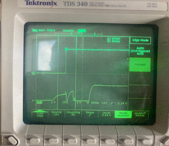
Testing on the 3 earlier Industrial BBBs, with my Cape power supply, I find the system won’t boot up reliably.
My power supply rise time is about 485u Seconds which looks reasonable to me. It has to power quite a bit of other circuitry on the Cape.
I scoped the power supply and the BBB SYS_RESETn P9-10 and saw more than one pulse on the reset causing a false trigger.
See IMG-1 attached.
I read page 57 of the BBB manual which describes the reset circuit and a problem which seems to match my problem.
I switched to the newer BBB boards I bought and the problem disappears. See IMG-2 attached. There is a stepped waveform on the BBB SYS_RESETn pin but only one reset pulse.
The BBB manuals states “On the revision A5D a change was made. On power up, the NRESET_INOUT signal can act as an output. In this instance it can cause the SYS_RESETn line to go high prematurely. In order to prevent this, the PORZn signal from the TPS65217C is connected to the SYS_RESETn line using an open drain buffer. These insure that the line does not momentarily go high on power up”
My questions are:
Can you confirm if my scope traces and descriptions match the BBB issue discussed on P57 of the BBB Manual?
When it states “On the revision A5D a change was made…”, is this the change which fixed the problem using “PORZn signal from the TPS65217C”?
I can’t identify a version number on any of my BBB PCBs which matches A5D? Can you please advise how I can identify which boards have a problem and which have the solution?
When purchasing BBBs from Element14 or Digikey etc… I am not sure how I can control when versions of board I will receive.
Is there easy cheap and cheerful solution I can add to my Cape to fix the reset issue.
For whatever reason, I couldn’t see your scope shots, but I’m doing something similar, though my issue involves the power not coming up at all.
My “failure to boot” comes from of the supply system I’m putting together running at about 4.2V for 150ms before finally turning on its own bypass letting the 5V flow properly. I mean I wasn’t even seeing D1 come on.
The bad news I discovered was that the TPS65217 PMIC has a requirement that the incoming power rise from below 100mV to at least 4.5V in 50ms, or power-on of the rest of the system isn’t guaranteed. And they meant it. If the power doesn’t come up fast enough, the BBB stays dark.
I wound putting together a power gate with a PMOS FET, an NPN, and a 3.9V zener.
It mostly works.
The zener has its own pull-down resistor before going to the base resistor of the BJT to put its voltage in line with the data sheet’s table. So, when the voltage gets to 4.6V the bottom of the zener will be around 0.7V and turn on the transistor that pulls down the gate of the PMOS FET, turning it on. Add a small cap to handle inrush issues, a pull-up to the gate to prevent initial turn on and and a pull-up from the output to the base to hold things on. And on the breadboard, it works. The power only goes on after the other PMIC gets itself together and the TPS65217 sees its quick power up.
Hi John
Thanks for your help.
I couldn’t see how to add images or attachments after I wrote my message.
Are you saying the requirement for rise time < 50mS is for the older BBB only and the new one it is not a requirement?
My cape dev boards I can manage with using the new BBBs which seem to work perfectly (I have 100% startup after 20 tests).
I have found the SYS_RESETn needs to start high, then go low for the reset, and then release back to high to work. I think the final spin for production I have a Tiny85 on my Cape and will use a GPIO line to provide an external reset (like above) after power stabilizes.
Can you (or someone) advise how to identify the version number on my BBB PCBs?
Thanks
Michael
The 50ms rise time requirement comes right out of the TPS65217 data sheet, and it’s in the boards we’ve bought which, without looking, are rev C. I’d have to go look over the documentation to see how to tell the version. I’m guessing it’ll be encoded on the label.
This morning I found the Rev number on the PCB. It is printed in copper rather than white screen print and is located under the power barrel connector.
The bad news for me is that both my good and bad boards are Rev B6. But the SYS_RESETn pin is very different on the two boards. My bad board is an Industrial BBB while the good board is the standard one.
The bad board looks like this. The top trace is my 5V being switched onto power the Beagle at VDD on header P9 pins 5 & 6. The bottom trace is the SYS_RESETn on P9 pin 10
The good board looks like this.
Both images show the Beagle is getting power from somewhere other than the VDD 5V which result in the SYS_RESETn starting to rise before VDD. I have voltages before this on my Analog inputs AINx and one GPIO line which I assume is causing this.
But the top image (bad board) shows SYS_RESETn dropping as soon as VDD is applied resulting in a double low reset pulse. The good board image shows SYS_RESETn held up for a period after VDD is up resulting in only one low reset pulse.
They just look different and sort of match the description in the Beaglebone black manual.
SYS_RESETn is rising before you apply power. That’s not good. You are likely placing a signal on one of the BBB P8/P9 I/Os before the BBB powers up and powering things through an ESD diode.
A UART is generally the culprit as people forget about them being powered on all the time.
Note that on the “bad” board your SYS_RESETn line has a lot of RC time constant rounding while the “good” board is pretty square. It looks likes there is a bunch of capacitance on the SYS_RESETn line coming from somewhere.
C24 sticks out as an “industrial” version likely doesn’t derate as much as a standard capacitor and you might have a factor of 2 or 3 in terms of capacitance difference.
Your problem echos one I’ve been also fighting, and buzmeg’s reply about putting voltage on the reset line makes perfect sense.
I’ve got an external 3.3V regulator that feeds the LCD and I2C buses before the supply gets stable enough to allow the 5V to get to the BBB.
I’m still fighting with the dedicated hardware guy one cube over from me to pull the supply for it and put it on either the 3.3V coming out of the BBB or at least on the held off 5V input.
I wound up playing the “pull wires until it started working” trick regarding the LCD signal lines. The BBB started to come out of reset once LCD_DATA0, LCD_DATA1, LCD_VSYNC, and LCD_PCLK lines were pulled. Plug a couple of them in and the console port would produce a volume of garbage instead of bootloader status information. Plug them all in, and the processor went into full-on 4Q mode.
In other words, I’m in the “don’t mess with the processor until after it’s gotten itself powered up and squared away.” camp.
Hi Buzmeg
Thanks for your response.
At present I don’t connect anything to the SYS_RESETn line. So any capacitance is on the BBB PCB itself.
I note your comments regarding voltages on the GPIO before power is applied. I have limited this down to 1 GPIO line now and minimized the time period it is applied. I have also added a 10K resistor in series as I found the GPIO line was adding a significant load when the power is off the Beagle, when I was expecting it to be high impedance.