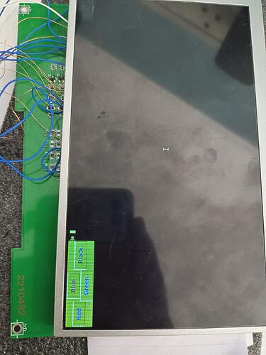
I have beagle board black in that i run linux source version “linux-5.4-rt” and successfully load “BB-BONE-LCD7-01-00A3.dtbo” file using u-boot(v2023.04) and lcd working on GPIO pin .
Problem :- currently i load overlay menually by using following command .
• setenv fdtaddr 0x87f00000
• setenv fdtovaddr 0x87fc0000
• load mmc 0:1 ${fdtaddr} am335x-boneblack.dtb
• load mmc 0:2 ${fdtovaddr} /lib/firmware/BB-BONE-LCD7-01-00A3.dtbo
• fdt addr $fdtaddr
• fdt resize 8192
• fdt apply $fdtovaddr
• setenv bootargs console=ttyO0,115200n8 root=/dev/mmcblk0p2 rw rootfstype=ext4 rootwait earlyprintk mem=512M
• load mmc 0:1 ${loadaddr} uImage
• bootm ${loadaddr} - ${fdtaddr}
every time when i reboot .
I want that overlay should load during boot autometically. So that my lcd work directly , Can any one have solution for this , please provide me.
if you are using a standard BBB uboot, just edit uEnv.txt and add the overlay in there.
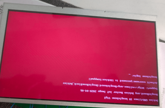
Thank you. I successfully change uEnv.txt file and it work, But i get Red colour LCD background in "BB-BONE-LCD7-01-00A3. I want black colour LCD back ground , can suggest solution for this .
This looks more like a bit shift from a panel that has a different RGB order on the 18 bit or 24bit data lines…
What lcd is this, is there a part number on the module?
Regards,
This is “https://cdn-shop.adafruit.com/datasheets/AT070TN94.pdf” datasheet link for LCD that i used.
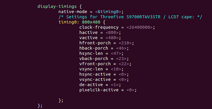
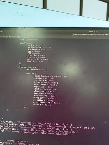
I also attached screenshort for pannel configration that i do .
That LCD looks to be a 24bit model… Are any model numbers on the PCB, like BeagleBoard.org LCD XYZ?
If it’s your own design, do you have a schematic?
BB-BONE-LCD7-01-00A3 is for 16bit lcd, so that’s where the crazy color shift comes from…
Regards,
For better conviant i attched "photo-1" , please see .
Currently i get display on gpio without using HDMI.
I am try to find solution of why i get red colour background
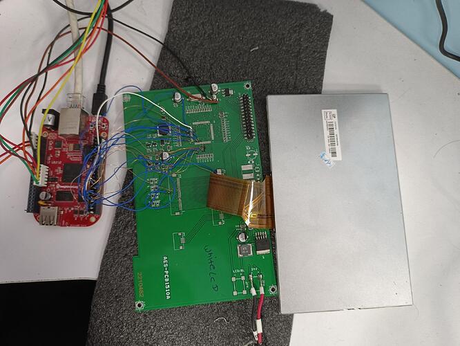
I attached “photo-2” it connection that i do for LCD ( we take GPIO LCD output from p8 in BBB, connect to our PCB so that we connect CSI cable in PCB and connect to LCD )
DocScanner Jul 7, 2023 12-28 PM.pdf (173.1 KB)
Are you using BB-BONE-LCD7-01-00A3.dtbo unmodified ?
If not paste the modified version here.
Is that photo the current state ? It looks to me you have only wired up 20 pins, is that correct ?
As it is a 24 bit display, are the lower bits connected together ?
As the display looks mostly correct I would try changing the sync-edge in the dtb file from 0 to 1
		panel-info {
			ac-bias           = <255>;
			ac-bias-intrpt    = <0>;
			dma-burst-sz      = <16>;
			bpp               = <16>;
			fdd               = <0x80>;
			sync-edge         = <0>;
			sync-ctrl         = <1>;
			raster-order      = <0>;
			fifo-th           = <0>;
		};
Also the timings in that file do not match very closely those of the display.
Page 14 of the datasheet lists the timings.
I think that HS Blanking is hback-porch, and VS Blanking is vback-porch.
I am not sure this is causing the colour shift though.
It is like it is latching data on the wrong edge, hence try changing the sync-edge value.
thank you. I change as per your suggestion and i get black background(not complitly).
Now to verify that we get propar colour generation or not . I run “tkinter” using “windoesX”
In that i run small python scrept in which i generate 4 button of different colour , But i don’t get propar color, please see image " tkinter_application.jpg"
please suggest any solution for this .
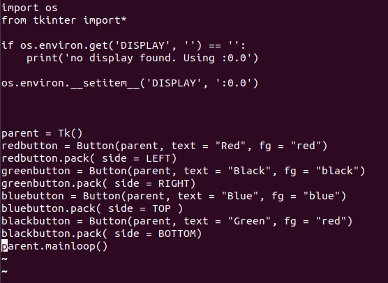
Pannel_configration = it is pannel configration that i do for my LCD work in “BB-BONE-LCD7
-01-00A3.dts”
login.jpg = it is image of login screen that i get . You can see it is not complitaly black .
tkinter_application.jpg = it is o/p screen that i get after runing python screen .
python_script_for_button_generation = o/p screen that i get after run script ( from that you will see i don’t get propar colour generation"
Are you connecting all the unused bottom LCD lines together ? The panel is a 24 bit panel, 8 x red, 8 x green, 8 x blue.
You are only wiring 16 bits. What are the unused pins connected to ? IF not connected they will be floating and causing problems.
Wrong colour is often caused because the colour order is sometimes different on displays. It can be RGB or sometimes BGR, resulting in red and blue colours being swapped.
Your test program sets the Green button text to red. Otherwise it looks to me like red and blue are swapped, as the Blue is showing as red.
There is an option you may need to add to the dts file.
See Documentation/devicetree/bindings/display/tilcdc/tilcdc.txt in the kernel source
panel {
        status = "okay";
        compatible = "ti,tilcdc,panel";
        pinctrl-names = "default";
        pinctrl-0 = <&bb_lcd_lcd_pins>;
        blue-and-red-wiring = "crossed"
hello ,
I successfully active gpio LCD , there is a some colour problem but that’s is ok,
Now i want to active touch , i use “BB-BONE-LCD7-01-00A3.dtbo” in that their is already touch fregment is their , i used this overlay and try to calibrate the touch using “tslib” but i get some problem ;
- to calibrate touch need to use command :- “ts_calibrate” i get screen with cross mark for touch but it take sample at very very low speed. and i think co-ordinate point is also not propar value .
2)After calibration this data should autometically in etc/pointercal but in my case it not write , so i menually write in pointercal .
- “tslib” provide one test to check wheter your touch propar calibrate or not i also run this but not getting proapr value .
so i want that please provide me step-by-step solution to active touch like
- On which pin of BBB i need to connect this x,y (4 wire) pins.
- this their any change in “BB-BONE-LCD7-01-00A3.dtbo” for touch ?
- Then how to calibrate this touch .
What is the touch control chip ?
How is it wired up ?
i attached photo in which it have doted circle , doted circel on BBB gpio is connction of axis pins .
AIN0 = x-axis(left) pins
AIN1 = x-axis(right) pins
AIN2 = y-axis(up) pins
AIN3 = y-axis(down) pins
second circle is about touch in GPIO lcd .
Basically in GPIO lcd have touch cable that go into our PCB from that we take wires and connect to BBB,
I want to use inter ADC .
Can you clarifi my douct in overlay “BB-BONE-LCD7-01-00A3.dtbo ” it have adc "fragment@6 " it is for internal ADC or external ADC.
Ok, just guessing here, but look at the dts file you are using.
There is a line that reads (unless you have modifed it)
ti,adc-channels = <4 5 6 7>;
I would expect these need to be set to 0 1 2 3 if you haven’t done so.
Read the documentation in
Documentation/devicetree/bindings/input/touchscreen/ti-tsc-adc.txt
In the lernel source directory to get some idea of the various parameters.
Potentially you may need to change the following
x-plate-resistance
wire-config
These are explained in ti-tsc-adc.txt
Assuming you have the touch input, there is a useful utility called evtest
This will print out the generated touches to the console so you can see if the touchscreen is actually working and giving you reasonable values.
