Hi,
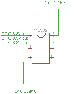
The circuit should look like something like this :
Which is OK if you want to run the input of a 5 volt TTL chip directly
from the BBB.
I'd advise against it simply because of paranoid engineering.
?
You also mentioned that I need to monitor voltages :
*"An analog multiplexer driving an op amp running from 1.8 volts" *
You mean that I need to use the onboard ADC ? But I have a problem, I don't
know how to use such a system (mux + opamp). Could you explain me a little
bit more please ?
(If this isn't BBB related (as in a project), then someone say so
please....
Ok, look at testing an IC, any IC, any pin can be the following:
1) input
2) output
3) bidirectional
4) ground
5) supply.
things not to do:
1) connect any pin on the processor to a source of voltage greater
than the processor's VCC
2) connect as output two pins (processor to chip) together (if in
opposite states, with active pullups, excessive current will flow,
letalone pulling up a pin on the processor too high.
3) try to supply the IC through a processor pin. Also trying to
ground the chip through the processor pin.
Kinds of faults you may see in the IC under test (assuming vcc and gnd
are connected elsewhere).
1) pin is open
2) pin is stuck at ground
3) pin is stuck at VCC
4) pin as output does not go to logic 1 (bad level)
5) pin as output does not go to logic 0 (bad level).
Try the following:
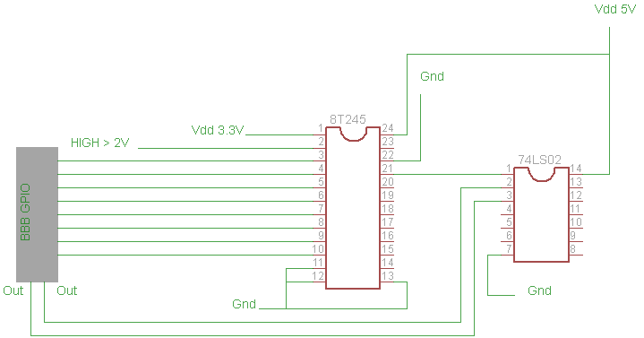
Running the processor to an open collector inverter allows the pin to
be grounded without harm, all that you are doing is grounding the
pullup resistor.
Using the level converter allows you to see a logic 1 or a logic 0 at
the chip pin.
However, sections 4 and 5 do not get covered.
What you'd like to do is measure the voltage at any pin with the
chip's A/D converter. The following scheme is used a lot to do just
that, with the operational amplifier protecting the far more expensive
processor.
The first thing is to realize that you want to measure more than one
pin. You could have a circuit for each pin, but that would limit you
to the 8 A/D channels.
You can use an analog multiplexer, it works like a digital multiplexer
(8 inputs selectable to 1 output), except that analog voltages go
through, rather than digital levels. Google "analog multiplexer".
This will run at the voltage levels of the IC (chip you're testing).
So for a single chip, you'd have 3 lines (binary selection) picking
which input gets selected.
This voltage appears at the output of the multiplexer. It's still (at
the worst) 5 volts or 0 volts. Too much for the processor.
You need a non-inverting opamp circuit (again, look it up) with a gain
of 1. This gives you a bit of margin. 5.0 volts at the input of the
opamp will give you 5 volts at the output. Run this through a
resistive divider with the ratio of 1.5/5.0. This gives you some
safety margin. In this case, it's ok to use a resistive divider since
you're not dealing with digital levels and it's one way only. This
goes to the A/D input. (chip is safe). Run the opamp from the 5 volt
supply going to the chip. (the opamp works as a buffer and minimizes
the load on the circuit)
Draw a block diagram, look at the voltages, then see what goes inside
each block.
You'll want one multiplexer input for each pin on the chip.
This is *if* you want to check the voltage levels on the chip. If
not, then what you've written (with an output driver I'd put in) would
be the reasonable thing to do.
Checking the voltage levels on the chip can help identify the chip,
and can also determine if you've got bad pins on the chip (that still
read 1 or 0, but not always a good 1 or 0).
More complicated than you were asking, but this is a direction the
design can go.
To simply take the design to the point where the chip can be directly
connected to the processor, use 3.3 volt capable logic. (back to the
simplest design).
Harvey