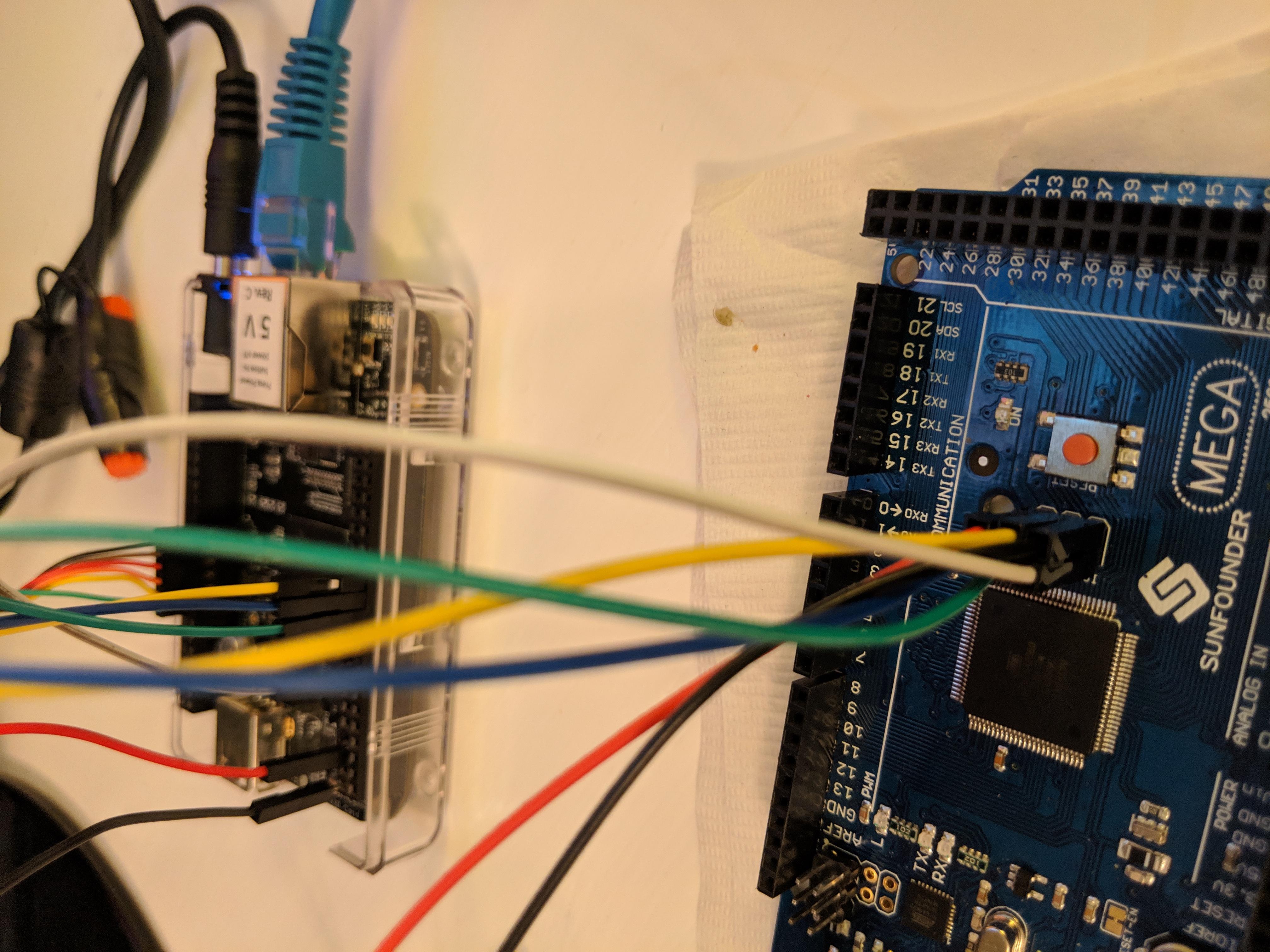
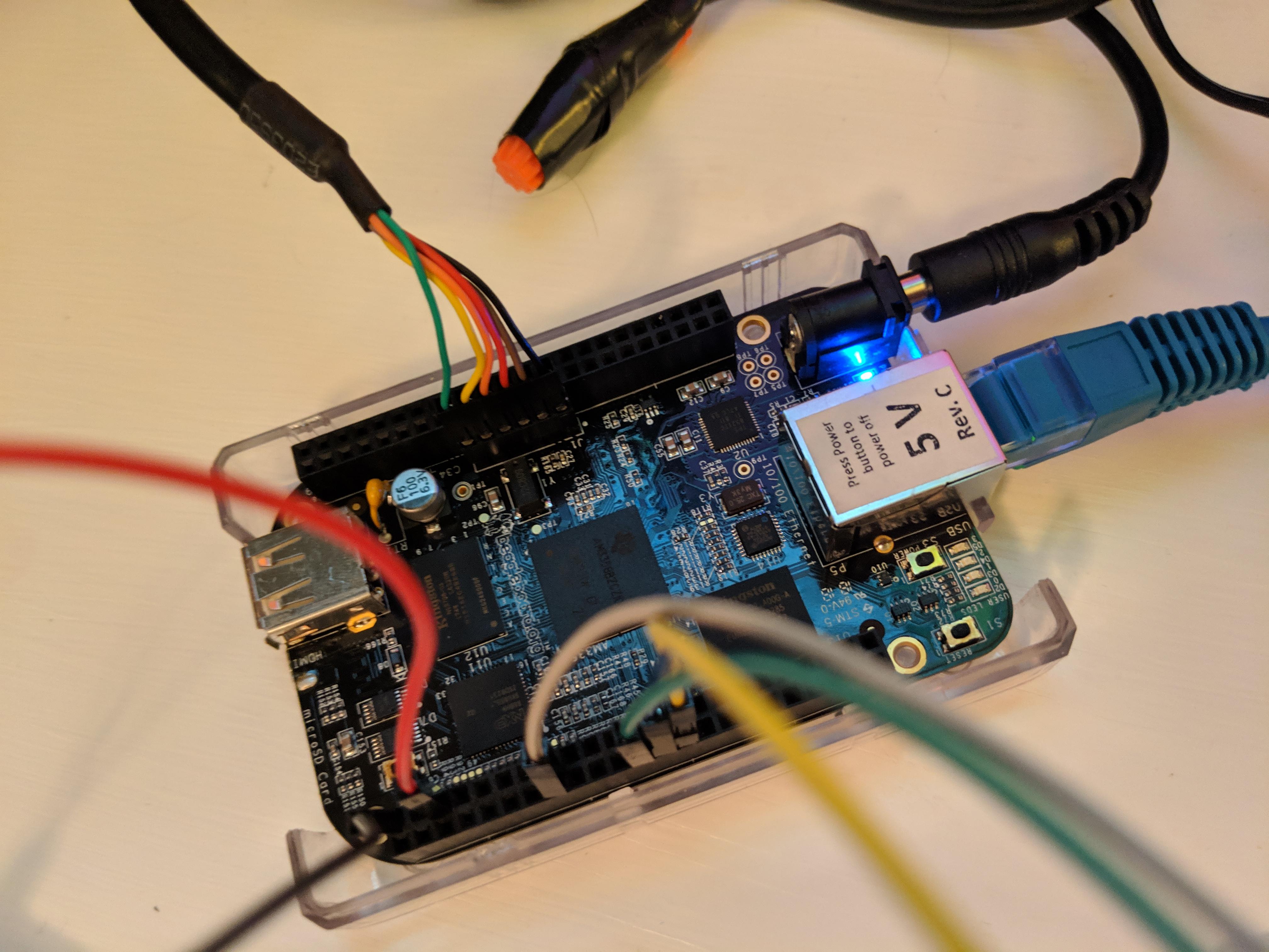
I have a device plugged in via GPIO to the following gpio pins:
48
49
115
117
If my device is connected at boot, the BB will not boot.
I am booting from eMMC. Any idea why this is occurring? I am using the attached custom overlay which is essentially the univ-emmc overlay with some modifications on GPIOs not listed above.
Mike
Gerald,
Thanks for pointing me to that information but I don’t see where I am utilizing one of the 16 boot pins on the expansion header.
Also, my external device that is connected to the GPIO listed above is not powered up at boot.
Am I missing another key point in the reference you pointed me to?
Mike
Yes. And sys_reset_n is just a RC-delayed version of the 3V3 supply. It is not debounced
if activated by the reset switch and rises slowly in the classic 1-e-function style.
You need a Schmidt-trigger if you want to use it as a logic signal.
That sys_reset_n is high does not mean that you may drive some pins
(in my case P8. 39-46, the 8 pins accessible to PRU1 and also used by the LCD.)
I found that I had to use an 74LVC244 for isolation; the 3stated pins of a
Xilinx Coolrunner II were not high-impedance enough.
When sys_reset_n goes away, the processor just starts; it has not yet made up
its mind where to boot from.
I used a time constant of 3 times sys_reset_n to enable the 74lvc244.
regards, Gerhard
It just take on boot pin to mess up the boot process. If it is not powered on it still presents a load. It still affects the boot pins.
Key point…DO NOT PUT ANYTHNING on GPIO pins that share the boot function on power up.
Gerald
But which gpio am I using that is a boot pin? In the reference manual, the 16 boot pins are on the P8 header... I'm using gpios on the P9 header.
Does anything show up over serial when it's plugged in? And what shows up?
Regards,
`
U-Boot SPL 2017.03-00002-gd12b1519b4 (Mar 14 2017 - 10:28:26)
Trying to boot from MMC2
mmc_load_image_raw_sector: mmc block read error
spl_register_fat_device: fat register err - -1
spl_load_image_fat: error reading image u-boot.img, err - -1
** ext4fs_devread read error - block
Failed to mount ext2 filesystem…
spl_load_image_ext: ext4fs mount err - 0
`
Then there must me somethig else at play here. Without a schematic, kind of hard to tell.
Looks like you may be conflicted with the eMMC pins, which also go to the expansion headers.

I do not know if the MMC ports are numbered 0 and 1 or 1 and 2 these days in SW. But normally the board boots from the eMMC. On the Hardware we numbered them 0 and 1, 0 being the SD card and 1 being the eMMC. You can insert a bootable SD card and see if it boots from there.
Gerald
From your picture, that’s the P8 header…
Regards,


HAH, wow it has been a long day. It must be time for me to put this aside for a bit… WOW. Sometimes I amaze myself.
Thanks and sorry that my goof has taken up a small bit of ya’lls valuable time.
Until my next stupid question…
Actually, one more question before I go cry myself to sleep…
Considering I will want to make similar connections on P8 in the future… can I use a device like this to isolate the boot pins at boot?
http://www.ti.com/lit/ds/symlink/sn74cbtd16211.pdf
In principle yes, but given that you won't need that many bits and that the BBB pins
are relatively weak drivers and the ground connections on the BBB are a joke, I prefer
74LVC244 / 74LVC245 or similar. They present less load to the BBB and are also much
more common, mainstream devices, and cheap.
Cheers, Gerhard
p.s.
Has anybody tested out what it takes to isolate that 16 bit multiplexed bus?


