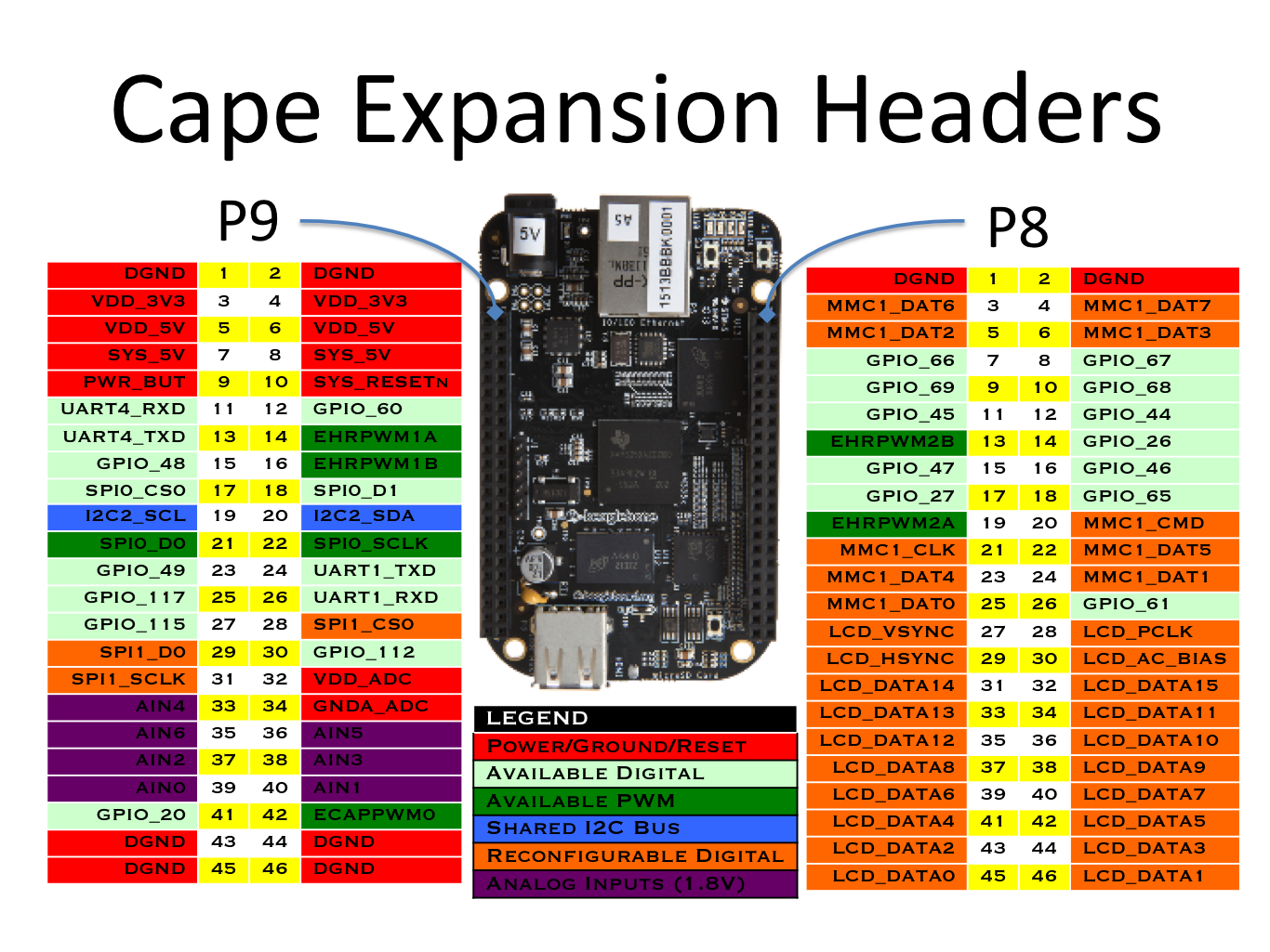
Use on Blue,Use on RC,P8 pin,Ball,Blue Name,Black Name,MODE0,MODE1,MODE2,MODE3,MODE4,MODE5,MODE6,MODE7
GND,GND,"1,2",,,,,,,,,,,
eMMC_DAT6,N/C,3,R9,MMC1_DAT6,GPIO1_6,gpmc_ad6,mmc1_dat6,,,,-,-,gpio1[6]
eMMC_DAT7,N/C,4,T9,MMC1_DAT7,GPIO1_7,gpmc_ad7,mmc1_dat7,,,,-,-,gpio1[7]
eMMC_DAT2,N/C,5,R8,MMC1_DAT2,GPIO1_2,gpmc_ad2,mmc1_dat2,,,,-,-,gpio1[2]
eMMC_DAT3,N/C,6,T8,MMC1_DAT3,GPIO1_3,gpmc_ad3,mmc1_dat3,,,,-,-,gpio1[3]
LED_RED,LED_RED,7,R7,GPIO2_2,TIMER4,gpmc_advn_ale,,timer4,,,-,-,gpio2[2]
LED_GRN,LED_GRN,8,T7,GPIO2_3,TIMER7,gpmc_oen_ren,,timer7,,,-,-,gpio2[3]
PAUSE_BTN,PAUSE_BTN,9,T6,GPIO2_5,TIMER5,gpmc_be0n_cle,,timer5,,,-,-,gpio2[5]
MODE_BTN,MODE_BTN,10,U6,GPIO2_4,TIMER6,gpmc_wen,,timer6,,,-,-,gpio2[4]
QEP_3B,QEP_3B,11*,R12,EQEP2B_IN,GPIO1_13,gpmc_ad13,lcd_data18,mmc1_dat5*,mmc2_dat1,eQEP2B_in,pr1_mii0_txd1,pr1_pru0_pru_r30_15,gpio1[13]
QEP_3A,QEP_3A,12*,T12,EQEP2A_IN,GPIO1_12,gpmc_ad12,lcd_data19,mmc1_dat4*,mmc2_dat0,EQEP2A_IN,pr1_mii0_txd2,pr1_pru0_pru_r30_14,gpio1[12]
PWM_2B (Mot4),PWM_2B (Mot4),13*,T10,EHRPWM2B,EHRPWM2B,gpmc_ad9,lcd_data22,mmc1_dat1*,mmc2_dat5,ehrpwm2B,pr1_mii0_col,-,gpio0[23]
LED_4,LED_4,14*,T11,GPIO0_26,GPIO0_26,gpmc_ad10,lcd_data21,mmc1_dat2*,mmc2_dat6,ehrpwm2_tripzone,pr1_mii0_txen,-,gpio0[26]
QEP_4B,QEP_4B,15*,U13,PR1_PRU0_PRU_R31_15,GPIO1_15,gpmc_ad15,lcd_data16,mmc1_dat7*,mmc2_dat3,eQEP2_strobe,pr1_ecap0_ecap_capin_apwm_o,pr1_pru0_pru_r31_15,gpio1[15]
QEP_4A,QEP_4A,16*,V13,PR1_PRU0_PRU_R31_14,GPIO1_14,gpmc_ad14,lcd_data17,mmc1_dat6*,mmc2_dat2,eQEP2_index,pr1_mii0_txd0,pr1_pru0_pru_r31_14,gpio1[14]
BATT_LED_1 (gpio 27),BATT_LED_1 (gpio 27),17*,U12,GPIO0_27,GPIO0_27,gpmc_ad11,lcd_data20,mmc1_dat3*,mmc2_dat7,ehrpwm0_synco,pr1_mii0_txd3,-,gpio0[27]
***A2DP_FSYNC,***A2DP_FSYNC,18,V12,GPIO2_1,GPIO2_1,gpmc_clk_mux0,lcd_memory_clk,gpmc_wait1,mmc2_clk,,pr1_mdio_mdclk,mcasp0_fsr,gpio2[1]
PWM_2A (Mot3),PWM_2A (Mot3),19*,U10,EHRPWM2A,EHRPWM2A,gpmc_ad8,lcd_data23,mmc1_dat0*,mmc2_dat4,ehrpwm2A,pr1_mii_mt0_clk,-,gpio0[22]
eMMC_CMD,N/C,20*,V9,MMC1_CMD,GPIO1_31,gpmc_csn2,gpmc_be1n,mmc1_cmd*,,pr1_edio_data_out7,pr1_pru1_pru_r30_13,pr1_pru1_pru_r31_13,gpio1[31]
This file has been truncated. show original


