Hi,
I am Meet Shah. I am using Beagle play board and I am facing Hardware related issues regarding PMIC providing incorrect output voltage.
On Power up Led glow and we are able to get 5V but we are unable to get any other output voltage from buck converters and LDOs
Can I get any assistance from beagle team for the following matter?
Is this a clone board, what image did you flash to the eMMC, what image are you trying to run?
Regards,
We also observed that the power switch for the SD card has its enable signal connected to the processor. As a result, the voltage measured at the SD card’s VDD pin was 0.22V. The same 0.22V reading was observed on the diodes (PWR_ENABLE_SD) and RESTARTZ, which are connected to both the processor and the power switch.
To address this, we removed the diode and provided a direct 3.3V supply to the power switch and then to the SD card. Would the removal of this diode create any obstruction in booting the processor?
We designed a custom board based on the BeaglePlay reference design, using all the open-source Altium export files available on GitHub. After assembling the board, we encountered issues with the power supply during testing.
To troubleshoot, we managed to supply power to the custom board through an EVM board. However, the board still does not appear to be booting, or we have no indication that it is booting since none of the user LEDs are lighting up.
We are flashing the board using the BeaglePlay Linux OS image via an SD card but have not observed any response.
-
Before flashing the board, do we need to configure any chips mounted on it? If so, how can this be done?
-
Regarding the PMIC, does it operate through I2C communication with the processor, or does it run with its default factory configuration after assembly?
We have also prepared an external 3.3V LDO supply (TLV62595D) to power LDO1 of the PMIC. We observed that when the enable pin (TLV62595) is pulled to 5V and connected to the GPO2 pin of the PMIC, the LED on the GPIO2 pin blinks momentarily and then turns off. This suggests that it is not receiving 3.3V, causing all power supply rails to show 0V, which likely indicates that the PMIC is shutting down.
Which exact AM625 did you use? GP, HS-FS, or HS-SE? The Play used GP, and you could not have gotten those, as TI no longer offers them. GP, HS-FS, HS-SE all require it’s own bootloader, you can’t boot a GP device image on HS-FS or HS-SE…
Regards,
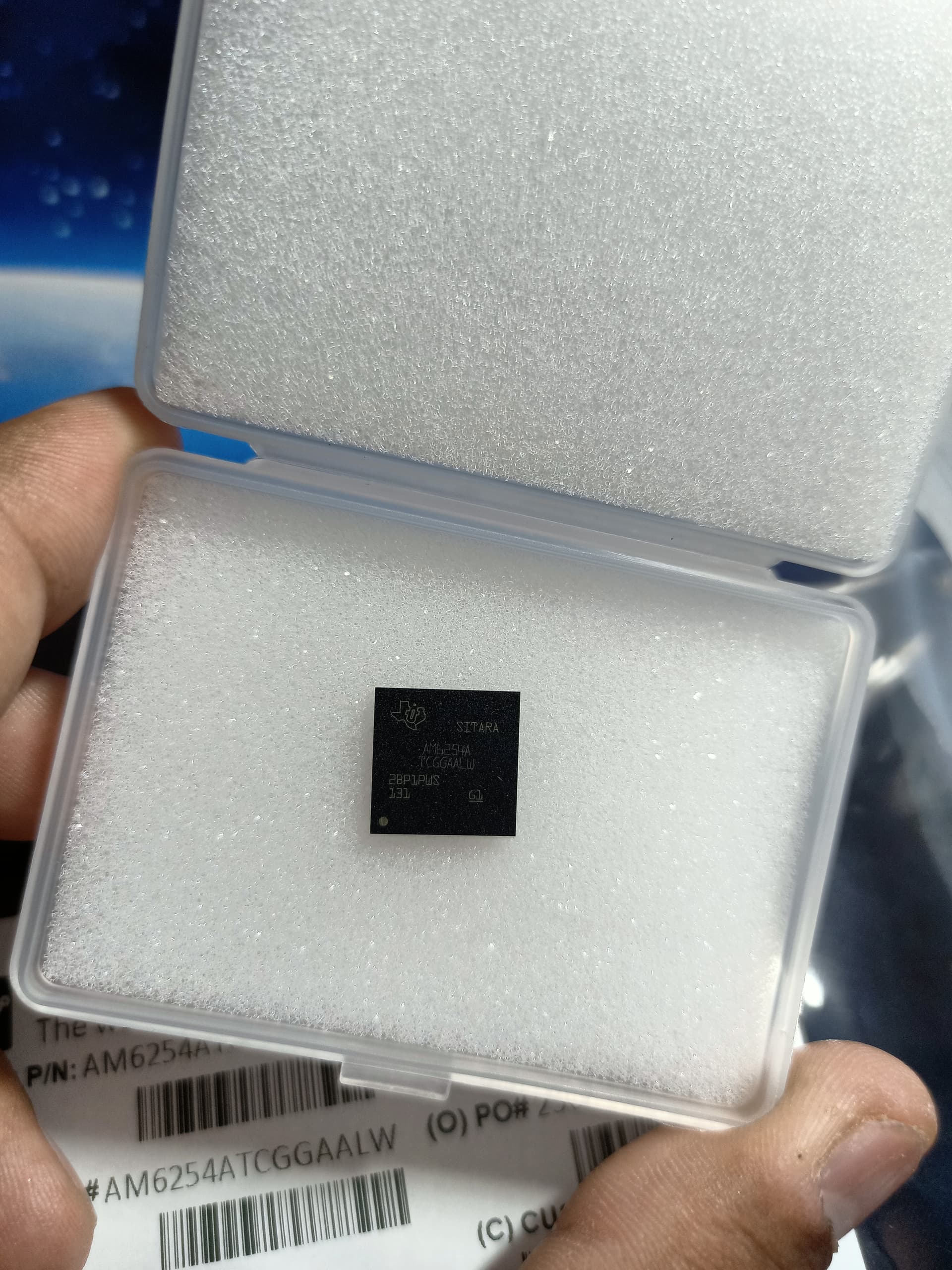
The part number AM6254ATCGGAALW corresponds to a GP (General Purpose) device based on Texas Instruments’ naming conventions and we are using same part number. Also in BOM of Beagleplay same part number is mentioned, still it does not boot
Where is it hanging? What does the debug port show?
We are unable to proceed with the debugging process due to issues with the power supply. The onboard power supply does not function, so we provided power from an EVM board. However, when powering on, the PMIC suddenly shuts down.
To identify the issue, we tested different output voltages and found that when Buck 2 (1.8V) is disconnected, the board powers up. We have checked for short circuits on the board and found none. Additionally, the GPO2 LED does not glow on the EVM board.
What could be the possible issue if the GPIO LED is not glowing? (The GPIO2 pin is attached to ENABLE pin which is pulled to power rail (5V) of external LDO (TLV62595)
If that is the evm the regulator is more than likely blown.
Your on board supply not working, is an issue. Better start there first, without good power you are not going to have much luck. If the power chip is dead or some discrete is dead/shorted it could be shorting out the bus. Until you get on board power working not much will work.
I see you have one chip, how did you solder that onto the board?
I am sending two videos one with buck 2 output voltage connected and another buck disconnected where in second video board get powered up but does not boot
https://drive.google.com/drive/folders/1wNn5iNPWH4B-8AayqnT9q7btvYElUH-u?usp=sharing
sharing you drive link
Which chip are you talking about Processor chip AM62X or chip on EVM Board?
The processor chip was soldered by pcb fabricator itself and in EVM board we can insert the chip in the case provided on board itself.
That should be soldered in place correctly, so many points to cover it would be impossible to debug any of this on a forum.
At this point it would be best to evaluate your main objective. Determine the sales volume of the product. Low to midrange sales volume consider using an SoM, the extremely difficult part of the design is already complete. Much more successful designing a carrier board and just plug in the SoM.
If its mid to high contact one of the many service providers in APAC and stipulate it works out of the box. Best solution until you get a handle on the market and customer perception of your product, just buy the Beagle Board and focus your efforts on a quality code and market penetration.
Hello Team,
Power Supply of the board works but still it does not boot. We are using SD card for booting. Do we require any configuration on hardware end for booting the board for first time.
Can I get any assistance from beagle team for the following question?
Nope… you could try holding the ‘usr’ button to ‘force’ microsd over ‘eMMC’ for the bootsel pins…
Regards,