BeagleV-Fire and PWM Pins are Exactly on What Header Pins?

I broke my board. So, I rebooted into a new”er” image and it works again. yay!

Outside of that idea… How am I supposed to know what exact header pin is the PWM pins that are available due to Linux?

I was going to read some oscilloscope messages and use a LED for testing. I have some source code that I derived a while back. I want to test it but the Max_Botix sensor is missing for now.

Update

I tried to do something that made no sense. I thought I could symbolically run a PWM script without PWM input to the BeagleV-Fire and receive some type of output on the oscilloscope. Blah. I am silly for it.

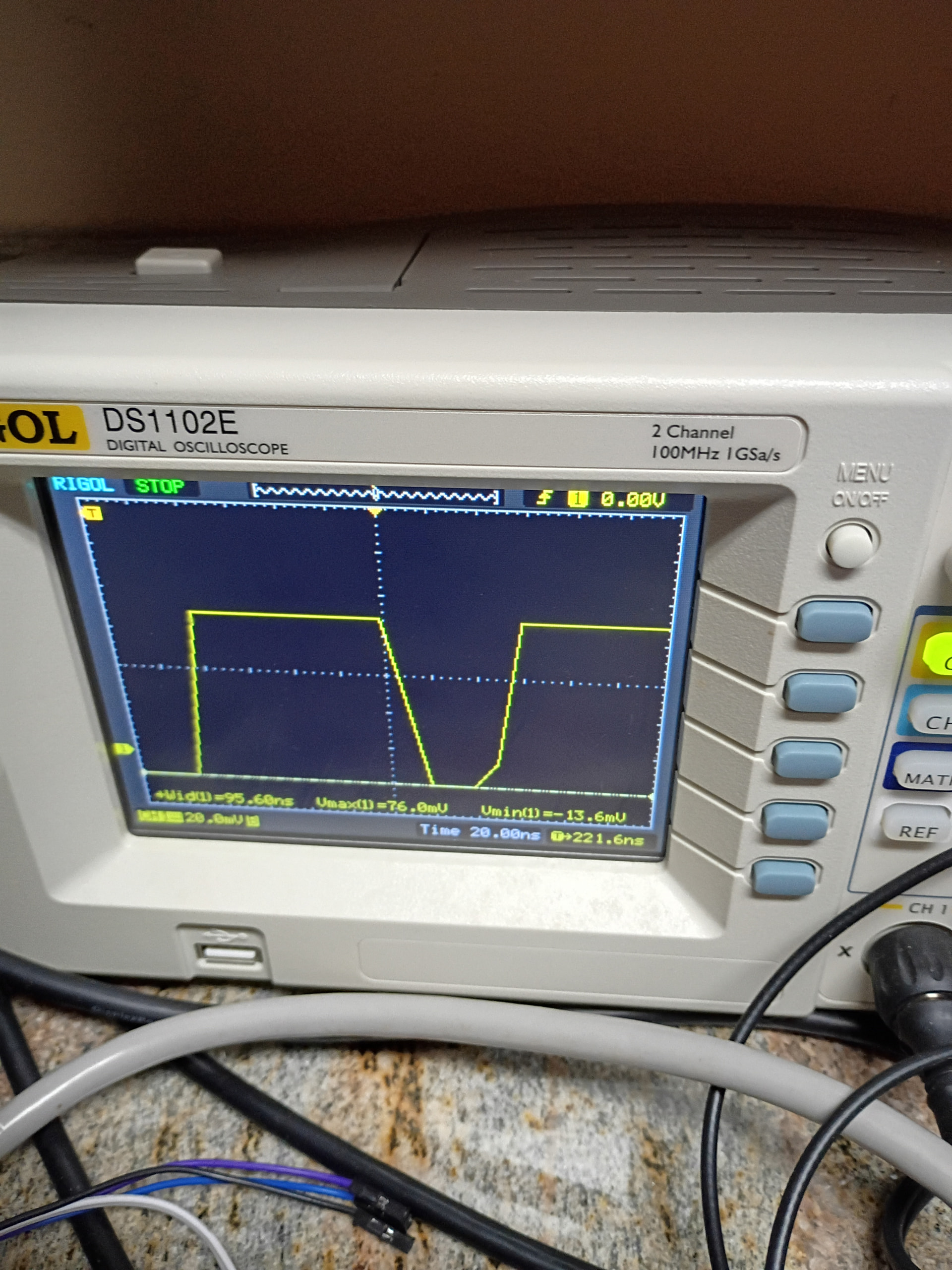
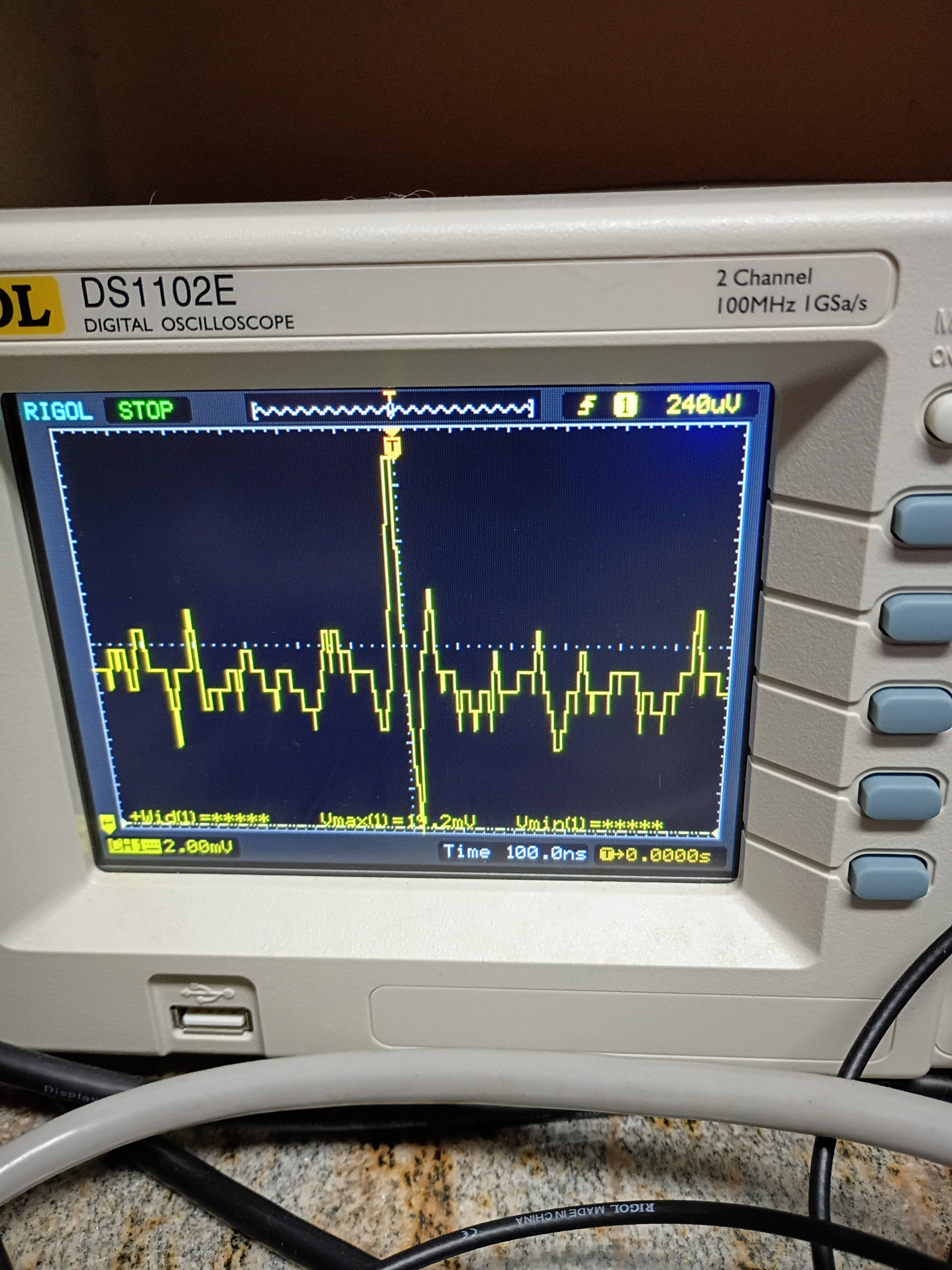
Anyway, I want to show what is happening on the pin in question: P9_42 and I think it is /dev/bone/pwm/1/a/*. I cannot be sure as of now. Completely guessing so far without any real procured data is my way for now. So, off to learn more and read some… But first is now. I will show the photo as I captured it with the following code:

and here is the source code for testing:

#!/usr/bin/python3

"""
This Code uses the:
* Maxbotic LV-EZ2 Ultrasonic Sensor

Tested with the BBBW
This sketch reads the LV-EZ2 by pulse count
Then prints the distance to the console

The circuit:
* 3.3v on the BBBW to LV-EZ2 Pin 7 Vcc
* GND on BBBW to the LV-EZ2 Pin 6 GND
* LV-EZ2 Ultrasonic Sensor PW pin to BBBW P9_14
* LV-EZ2 Sensor PWM usage!
"""

from time import sleep
import sys

PWM_E = "/dev/bone/pwm/1/a/enable"
PWM_D = "/dev/bone/pwm/1/a/duty_cycle"
PWM_P = "/dev/bone/pwm/1/a/period"

PWM_E == "0"
PWM_D == "1000000"
PWM_P == "25000000"

# calculated mode or median distance
mode_result = 0

# storing multiple pulses
# read in time for pin to transition
samples = 9
pulses = (PWM_E == "1", len==samples)

# sensor reads which are in range will be stored here
rangevalue = [0, 0, 0, 0, 0, 0, 0, 0, 0]

# 1s sensor power up pause
sleep(1)


def tof_cm(time_of_flight):
    """
    EZ1 ultrasonic sensor is measuring "time of flight"
    Converts time of flight into distance in centimeters
    """
    convert_to_cm = 58
    cm = time_of_flight / convert_to_cm

    return cm


def tof_inches(time_of_flight):
    """
    EZ1 ultrasonic sensor is measuring "time of flight"
    Converts time of flight into distance in inches
    """
    convert_to_inches = 147
    inches = time_of_flight / convert_to_inches

    return inches


def find_mode(x):
    """
    find the mode (most common value reported)
    will return median (center of sorted list)
    should mode not be found
    """
    n = len(x)

    max_count = 0
    mode = 0
    bimodal = 0
    counter = 0
    index = 0

    while index < (n - 1):
        prev_count = counter
        counter = 0

        while (x[index]) == (x[index + 1]):
            counter += 1
            index += 1

        if (counter > prev_count) and (counter > max_count):
            mode = x[index]
            max_count = counter
            bimodal = 0

        if counter == 0:
            index += 1

        # If the dataset has 2 or more modes.
        if counter == max_count:
            bimodal = 1

        # Return the median if there is no mode.
        if (mode == 0) or (bimodal == 1):
            mode = x[int(n / 2)]

        return mode

try:
    while True:

        # wait between samples
        sleep(0.5)

        if len(pulses) == samples:
            j = 0  # rangevalue array counter

            # only save the values within range
            # range readings take 49mS
            # pulse width is .88mS to 37.5mS
            for i in range(0, samples):
                tof = pulses[i]  # time of flight - PWM HIGH

                if 880 < tof < 37500:
                    if j < len(rangevalue):
                        rangevalue[j] = tof_cm(tof)
                        j += 1

            # clear pulse samples
            pulses.clear()  # clear all values in pulses[]

            # sort samples
            rangevalue = sorted(rangevalue)

            # returns mode or median
            mode_result = int(find_mode(rangevalue))

            # python console prints both centimeter and inches distance
            cm2in = .393701
            mode_result_in = mode_result * cm2in
            print(mode_result, "cm", "\t\t", int(mode_result_in), "in")

            # result must be in char/string format for LCD printing
            # digit_string = str(mode_result)

            sleep(2)
except KeyboardInterrupt:
    print("mode is ", mode_result, "cm... ")
    PWM_E == "0"
    pass

If you see my error, please let me know. I tried maxlen but it seems it is some sort of collections and deque library for now. I thought it was part of Python but I was wrong.

I just saw the readme.md file. Yes!

Not going to debug code for you, and nothing meaningful can be said without
knowing what Gateware is loaded, so let me generalize as much as possible:

BeagleV-Fire isn’t like the other beagles, where you have a selection of
fixed-function devices, attaching to the pads, through a PINMUX register.

Every single pin is exactly what you want it to be, so as you finally figured out,
every variant of Gateware come with it’s own readme.md, where this information is available.
How it maps to drivers inside Linux is another matter; here you’ll have to look
at what comes out of the debug port (or dmesg) and correlate that to the logical name.

1 Like

Gotcha. Okay. No issue about the debugging of the source code. No issue whatsoever.

Also, thank you for this data. Now, I know. My gateware is 2025.10-2-g4e16f48.

@lranders , do you think an oscilloscope would get in the way of running some source?

I have my positive probe to a resistor and the GND alligator clips to the LED for testing. Would you in practice use an oscilloscope with an LED or go with bare wire from the header pins of the BeagleV-Fire?

My first question, the part about getting in the way, is due to using echo to handle duty_cycle and period and then enable in the files and getting no output from the LED.

I don’t see how probing with a scope would disrupt the operation of the board,
but it does sound a little scary that you’re connecting that alligator-clip
to anything except GND.

All the LED outputs are routed to the pin-header, so it doesn’t make sense
to measure anywhere else.

I take it you’re trying to see the output of LED 10?

Seeing how PWM1 is connected to the 150MHz clock,
it’ll be going way too fast for your eyes to “see” anything…

1 Like

I am using /dev/bone/pwm/1/a/ as the file(s) needed.

Okay. Now, GND is on GND and P9_14 is on the Positive Probe.

Right, so you’ll need to attach to whatever the logical device for address 0x41400000 is.

1 Like

/sys/class/pwm/pwmchip0/pwm0 is where the locations of the files needed are located.

I tested here earlier and had the wire off by one line. Anyway, here is the squarewave.

That looks very odd indeed. Why are you at 20mV per division?

You should expect to see a voltage-swing of about 3.3V…

1 Like

No clue. I can change it but I am not exactly sure what it should be now…

Go with 2V/div and make sure your probe and scope matches it’s probe-divisor…

1 Like

I am set at 2v/div now and 5.00us on the timescale. My probe is reading 10.4mV? Is that right? Or is that doubled? For instance, 5.2mV per pin seems normal right?

No, a voltage swing of 5mV is just noise or crosstalk. You aren’t measuring anything.

Set the probe on one of the LED outputs and watch how that tracks 3.3V / 0V.

I am measuring the PWM signal. I can see the LED light up…

See? Much better! Now adjust that trigger point to be approx. 1.5V to avoid switching noise.

It is so small. I cannot see anything…

I cannot read that…

Does this vision and reading make any sense? The LED is on and I see no square waves…

I got it. I am surprised to see spikes and low lows outside of my square waves.

Alright, last photo with the fix and I will call this “conundrum” solved.

I may be getting static and noise on the Channel 1 from an unused Channel 2. Blah. I need to double check without Channel 2 attached while I only use Channel 1.

This is a post I made this morning. It seems simple enough to grasp to me. Plus, there are tidbits of “humor” in it. It showcases the BeagleV-Fire model, some questions, and a “lengthy” set of instructions to get up and running.

If anyone wants to look, there it is now. If you have comments, please direct them at me. Critique or whatever, fair game.

update

Also, I saw in the documentation at docs.beagleboard.org that there is a Buildroot kernel to behold and build. When I have time, I will update that small post from above with Buildroot jargon!