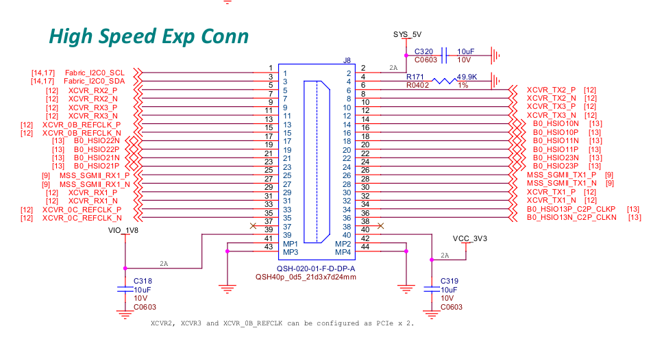
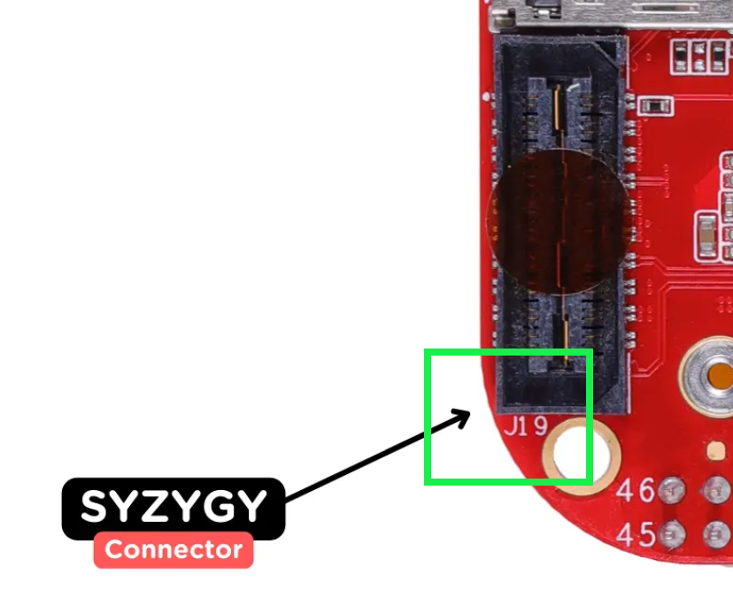
The schematic for the BeagleV-Fire shows the Syzygy connector as J8 but the picture of the board shows J19. See images below.
Which is correct?
The schematic for the BeagleV-Fire shows the Syzygy connector as J8 but the picture of the board shows J19. See images below.
Which is correct?
I cannot make sense of this board marking. There is no J19 connector on the schematics. I thought may be it was J1…9. But J1 is on the opposite side of the board (5V supply). I think it is simpler to ignore the J19 board marking for now and assume it should read J8.
I’m not sure why “J19” appears on the bottom of the board, but the SYZYGY connector shows as J8 in the PDF placement guide provided with the PCB design files. I suspect the “J19” is manually created/placed text and got out of sync with the design.
Note: I’m working on a SYZYGY expansion card and will release my KiCad design files when finished. I have noticed both the BeagleV-Fire and the SYZYGY KiCad example layouts have some very “odd” placements (not on any English or Metric grid near as I can tell) and the SYZYGY connector location on the TXR example is not (quite) correctly located per Opal Kelly’s own documentation.
Thanks for the comments. I guessed right.