BeagleY-AI pinmux for GPIO PD/PU configuration

Hi,
I’m currently struggling with a fairly basic problem.
I want to use a GPIO of the BeagleY-AI via gpio-key driver as a trigger.

For a quick test, I tried using the internal pull-up, so that I wouldn’t need to use an external pu.

Inside k3-am67a-beagley-ai.dts I added the following node.

gpio-keys {
	compatible = "gpio-keys";
	pinctrl-names = "default";
	pinctrl-0 = <&hat_36_gpio_pu>;
	
	key {
		label = "S1-BTN";
		/* HAT 36 (GPIO 16) */
		gpios = <&main_gpio1 7 GPIO_ACTIVE_LOW>;
		linux,code = <30>;
	};
};

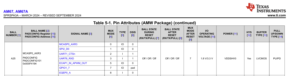
Inside k3-am67a-beagley-ai-pinmux.dtsi is the already existing definition for HAT Pin 36 with GPIO PU definition:

hat_36_gpio_pu: hat-36-gpio-pu-pins {
	pinctrl-single,pins = <
		J722S_IOPAD(0x194, PIN_INPUT_PULLUP, 7) /* (A25) MCASP0_AXR3.GPIO1_7 */
	>;
};

The event node is created and useable, so no issue here.

$ ls -l  /dev/input/by-path/platform-gpio-keys-event 
lrwxrwxrwx 1 root root 9 Aug 11 08:49 /dev/input/by-path/platform-gpio-keys-event -> ../event0

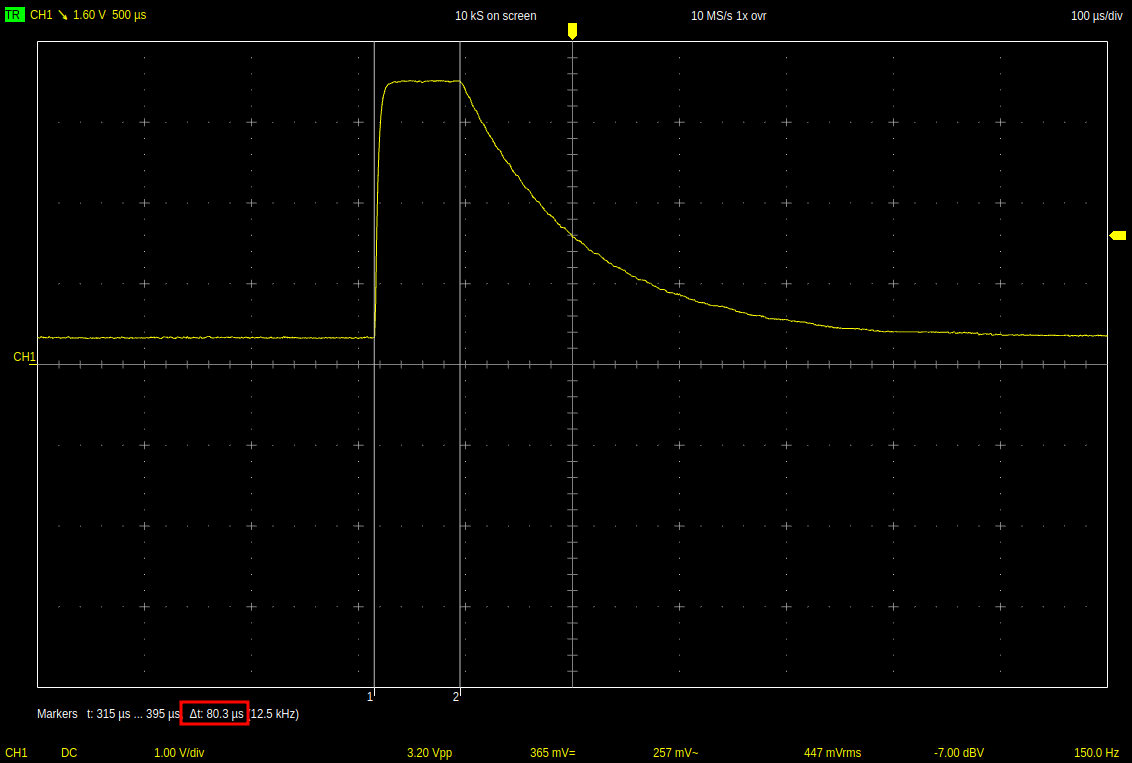
However, regardless of the configuration (pu/pd), the pin is always floating.
Of course I could use an external PU resistor, but I just wonder why that config has no effect.

Does anyone know if I’m missing something or have misunderstood something?

This might be a red herring, but the only thing that springs to mind is that there’s another
pinctrl directive hitting the same pin.

You could check this by using devmem2 to carefully examine the pinctrl register 0x194.
Visit the TRM for a full description of the bit-layout and how to calculate the true address.

I forget if BeagleY-AI also employs the “multi-ball” trick, but that can be found
out by checking the schematic for the pin in question. You might have to check for multiple drivers.

Thanks for the hint, I checked it and tried to understand the behavior.

It seems that the gpio-keys driver overrides somehow the pinctrl during initialization.

I can see with an oscilloscope that the pin is configured with a pu for some µs before the pinctrl is than again overridden (register changes from 0x60007 to 0x50007).

pinctl_pu_issue

When I move the pinctrl definition to other device-tree nodes the pu stays active or gets overridden depending on the order of driver probing.

Also when I comment out the definition of the gpio withing the gpio-keys definition the pinctrl definition with pu stays active. But then of course the key doesn’t work.

I also played around with Bitflags like shown below. But this didn’t help either.

gpios = <&main_gpio1 7 (GPIO_ACTIVE_LOW | GPIO_PULL_UP)>;

Any ideas where my mistake using gpio-keys is?

Try having a look at the gpio-keys linux driver.

Perhaps that will give you a clue to what exactly it is looking for in the device-tree.

I’m now getting closer to understanding the root of the issue.

I checked the driver and didn’t find anything unusual, so I wrote a short C program to see if the same behavior occurs when requesting a line via libgpiod.
In fact, I can reproduce the same behavior.
Whenever I do something like

gpiod_line_request_input(line, CONSUMER);

or even with defined bias

gpiod_line_request_input_flags(line, CONSUMER, (GPIOD_LINE_REQUEST_FLAG_ACTIVE_LOW | GPIOD_LINE_REQUEST_FLAG_BIAS_PULL_UP));

the pinctrl gets overridden and the pin is floating.

Interestingly, the given flags are recognized. This can be seen by checking the state with gpioinfo after requesting the line. However, the bias definition doesn’t have any effect.

...
line   7:     "GPIO16" "gpiod-example" input active-low [used pull-up]
...

I understand that libgpiod needs to configure the pinctrl, but why does it ignore or fail to work with the bias?

Does somebody know I that is expected behavior?

1 Like

from gpiod.line import Bias, Edge

@martin_hoehn , if you write up a python file use the directive listed above.

That should help with the bias and/or edge of the gpio pins in question.

Also, I noticed with libgpiod-dev and gpiod on the BeagleY-AI, gpioinfo reports back something different.

So, instead of chip and line, it has a GPIO14 and etc.

Seth

From what you’re describing, you might actually have found a bug.

Where it actually is, can be a little harder to ascertain.

One would have to trace from where libgpiod finds the [*pull-up] status.

One thing you neglected to mention is if you have checked the value of the underlying
hardware register at the same time as you’re running gpioinfo.
That could be helpful…

Unfortunately, I don’t have BeagleY-AI, so I can’t check any of this myself.

Thanks for your help!

@silver2row
I did a test using the Python library, but same behavior. So whenever a line is requested the pinctrl is overridden and the bias is ignored (at least for pinctrl).

Maybe I got you wrong, but regarding the report of gpioinfo everything looks fine to me.
Besides of the fact that the pinctrl is not handled correctly.
So in my case GPIO16 is just the line-name given inside the device-tree to match with RPI header naming.

RPI - HAT 36/GPIO16
BeagleY-AI - HAT 36/GPIO16

&main_gpio1 {
	pinctrl-names = "default";
	gpio-line-names = "", "", "", "", "", /* 0-4 */
			  "", "", "GPIO16", "GPIO17", "GPIO21", /* 5-9 */
			  "GPIO20", "GPIO18", "GPIO19", "GPIO15", "GPIO14", /* 10-14 */
			  "GPIO5", "GPIO12", "GPIO6", "GPIO13", ""; /* 15-19 */
};

In Linux main_gpio1 is then available via /dev/gpiochip3, which is probably just due the order of probing.

$ sudo gpiodetect 
gpiochip0 [tps65219-gpio.1.auto] (3 lines)
gpiochip1 [4201000.gpio] (24 lines)
gpiochip2 [600000.gpio] (87 lines)
gpiochip3 [601000.gpio] (73 lines)
main_gpio1: gpio@601000 {
	compatible = "ti,am64-gpio", "ti,keystone-gpio";
	reg = <0x00 0x00601000 0x00 0x100>;
	gpio-controller;
    ....
};

@lranders
I checked the pinctrl register and the physical level of the pin before and after requesting the line via libgpiod.

Before requesting line with libgpiod:

Pin state Pinctrl register Output gpioinfo
Pulled up 0x00060007 line 7: “GPIO16” unused input active-high

When line is requested:

Pin state Pinctrl register Output gpioinfo
Floating 0x00050007 line 7: “GPIO16” “btn-python-example” input active-high [used pull-up]

When line is released:

Pin state Pinctrl register Output gpioinfo
Floating 0x00050007 line 7: “GPIO16” unused input active-high

For now I will go with an external PU.
But when I have some spare time I will try to understand how gpioinfo finds the flags and why the flags don’t have any effect.

Interesting observation:
Both bits 16 and 17 change at the same time.

I wonder if the pins are in fact not floating at all, but pulled-down if not pulled-up…
Time to consult with the TRM!

I also wonder if gpioinfo is able to show PU/PD status at all if the pin is unused.

Question: If you request PD instead of PU, does gpioinfo show that at least?

In TRM I didn’t found the description of the bits inside the pinctrl register.
Any hints where I can find it?

I worked with the defines from k3-pinctrl.h which I assume are correct.

Here we can see that bit 16 is used to enable/disable the internal pu/pd and bit 17 is used to switch between pu/pd in case bit 17 is set.

#define PULLUDEN_SHIFT		(16)
#define PULLTYPESEL_SHIFT	(17)

//...

#define PULL_DISABLE		(1 << PULLUDEN_SHIFT)
#define PULL_ENABLE		(0 << PULLUDEN_SHIFT)

#define PULL_UP			(1 << PULLTYPESEL_SHIFT | PULL_ENABLE)
#define PULL_DOWN		(0 << PULLTYPESEL_SHIFT | PULL_ENABLE)

0x00060007:
PULLTYPESEL_SHIFT=1
PULLUDEN_SHIFT=0
→ PULL_ENABLE & PULL_UP

0x00050007:
PULLTYPESEL_SHIFT=0
PULLUDEN_SHIFT=1
→ PULL_DISABLE

I checked now also the register when I set pinctrl initially to Pull-Down.

0x00040007:
PULLTYPESEL_SHIFT=0
PULLUDEN_SHIFT=0
→ PULL_ENABLE & PULL_DOWN

Also when I use gpiomon I see that the pin is floating, because it detects sometimes quite fast level changes although I just connected a probe.

Regarding gpioinfo:

Before requesting line it shows only that it is configured as input.
→ So it doesn’t show the Pull configuration.

line   7:     "GPIO16"       unused   input  active-high

When line is requested, it show the configuration I selected. But this doesn’t match the physical level and pinctrl register value.

This time I used gpiomon for requesting.

# sudo gpiomon --bias=pull-down -f 3 7
line   7:     "GPIO16"    "gpiomon"   input  active-high [used pull-down]

# sudo gpiomon --bias=pull-up -f 3 7
line   7:     "GPIO16"    "gpiomon"   input  active-high [used pull-up]

# sudo gpiomon --bias=as-is -f 3 7
line   7:     "GPIO16"    "gpiomon"   input  active-high [used]

→ We can see with gpioinfo the selected Pull type.

Right, I was able to dig up a little more:
image

Still searching for the register bits defines; CoPilot thinks that the PULL_ENABLE should be active high, but I’m still looking for definite proof of that.

Why is PU/PD Enable the only bit to be reversed; I am puzzled…

1 Like

Did you guys ever figure it out? I was researching ideas and came upon this tidbit: https://www.kernel.org/doc/html/v5.4/driver-api/gpio/driver.html

It is not my current kernel but it is jam packed.

Seth

P.S. If I figure out the ins and outs and other stuff, I will try to find this post once more. From what I can tell, the older kernels have the builds but with current kernels, I did not find regmap. Maybe go further back in time. Sorry. You were right, I may not be of any assistance now. I mean…it has to be there but I could not find it again.

Small update from my side.

I created a post about that topic in TI’s E2E forum.

There is no final answer yet about the cause of this behavior, but they will investigate it further.

Sounds good. Keep us posted on any updates! :smile: