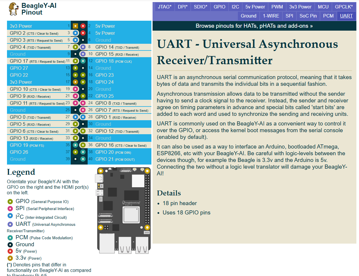
iam using BeagleY-AI in the board i performed UART loopbback using pin8,9 (/dev/ttyS3) it will execute. so ia want to access another uart using different pins but it accessible . can anyone tell how it will be access. i will attach pins diagram. please help me
I can only give hints…
// SPDX-License-Identifier: GPL-2.0-only OR MIT
/*
 * DT Overlay for /dev/ttyAMA0 uart pins within the expansion header.
 *
 * Copyright (C) 2023 Texas Instruments Incorporated - https://www.ti.com/
 *
 */

/dts-v1/;
/plugin/;

#include <dt-bindings/gpio/gpio.h>
#include "ti/k3-pinctrl.h"

/*
 * Helper to show loaded overlays under: /proc/device-tree/chosen/overlays/
*/
&{/chosen} {
        overlays {
                k3-am67a-beagley-ai-uart-ttyama0.kernel = __TIMESTAMP__;
        };
};

&main_uart1 {
        symlink = "ttyAMA0";
        pinctrl-names = "default";
        pinctrl-0 = <&main_uart1_pins_default>;
        status = "okay";
};
See how it is listed in kernel dtb-6.12-Beagle but I am on kernel 6.1.x.
So, I am not sure how things will actually work now unless I test.
Seth
P.S. I have been reading some classy notes in devicetree.org and omap bindings for now. If you look at /opt/source/, you will see some files. Check on them and see what is available… I will try to update you later on if I can configure things properly.
Thank you for the explanation. I checked my system and here are my findings:
-
Kernel version: 6.1.83-ti-arm64
-
UART devices present:
/dev/ttyS0 /dev/ttyS1 /dev/ttyS2 /dev/ttyS3 /dev/ttyS6 -
From
dmesg, the active UARTs are:serial@2800000 → ttyS2 serial@2810000 → ttyS3 serial@2860000 → ttyS6
So the UART controllers are enabled and detected by the kernel, but the pins are not muxed yet, which is why there is no signal on the header pins.
I understand now that I need to apply a device tree overlay to configure the pinmux for the required UART (for example main_uart1 / ttyS3).
Could you please confirm:
-
Which UART instance maps to which BeagleY-AI header pins?
-
Whether there is an official or recommended DTS overlay for enabling UART pins on BeagleY-AI (or an example I can modify)?
-
How can I correctly enable a UART loopback test (TX–RX) using these UARTs? (or) What is the recommended way to enable UART pinmux for these ports (device tree overlay or other method
Thanks for your guidance.
#include "ti/k3-pinctrl.h" has some files to review for making a DTS file.
There are some files I am not 100% knowledgeable on right now within k3-pinctrl.h.
I did see where some of the am62xx files are very similar to other 64-bit DTS files on other boards from beagleboard.org.
It is really hard for me to say right now what is what for now. I mean, /opt/source/ does not have the 6.1.x kernel available for testing DTS files for now. So, I am no help right now.
Seth
I am using a BeagleY-AI board and I want to interface it with a 7-inch Waveshare DSI LCD (H version).
Could you please guide me on the following points:
-
Which cable is required (pin count, pitch, and type – e.g., 22-pin / 15-pin FFC, A-type or B-type)?
-
Does the Waveshare 7-inch DSI (H) display require any power or backlight control configuration separately?
-
What is the device tree configuration / overlay required to enable the DSI interface and panel?
-
Are there any reference DTS files or examples available for BeagleY-AI + DSI LCD?
-
After enabling, how can I verify that the display is detected and working?
Any documentation links, example overlays, or known working steps would be very helpful.
Thank you.
Look on the board and in the docs.
Update
I know you are looking for DSI. I see the CSI camera but nothing for output.
I think the OLDI display interface may work. I am sure you want to display things (DSI). Hopefully, others will chime in.
Also, if you have not looked on your board:
- Try these
- k3-am67a-beagley-ai-lincolntech-185lcd-panel.dtbo
- k3-am67a-beagley-ai-dsi-rpi-7inch-panel.dtbo
Enjoy!
Kindly request your help with interfacing a 7-inch Waveshare DSI (H) LCD with the BeagleY-AI board.
I understand from the documentation that CSI camera support is available, but I could not find clear guidance for DSI display output. I would really appreciate your help in clarifying whether DSI display output is supported on BeagleY-AI and, if so, how it can be enabled.
If possible, could you please advise on:
-
Whether the 7-inch Waveshare DSI (H) display can be used with BeagleY-AI
-
Required cable type and connector details
-
Necessary device-tree or driver configuration
-
Or, if DSI is not supported, the recommended display interface (OLDI or HDMI)
Your guidance would be very helpful for moving forward with this setup.
Thank you very much for your time and support.
1 Like
I think someone once knew or maybe you know how to reverse the DTS files to look up the interior of the .dtbo. Now, I used to know but my records have been wiped clean for whatever reason.
I cannot remember who knows this specific command or if the command is available to look up but:
- Those DTBO files need to be in human readable format
- DTS
- The DTS (dtb) and DTSI (dtbo) files all should have similar acquired technology in human readable format from specific sources.
I am pretty sure those files go along with what I have typed. I will research the command but I will come up short (as usual). I think the idea is to reverse a dtbo to dtsi. Let me check. I am not even sure if that is available or if it works as is…
dtc -I dtb -O dts -o output_file.dts input_file.dtbo and then rename the .dts to .dtsi and etc.
I will review the command I shared via some research via google and then tell you if I can do anything with any of the file(s) in question.
Hi,
I have two issues where I need help with the BeagleY-AI board:
 7-Inch DSI Display Not Turning On
I am trying to use a 7-inch Waveshare DSI (H) LCD with the BeagleY-AI.
I enabled these overlays:
k3-am67a-beagley-ai-dsi-rpi-7inch-panel.dtbo
k3-am67a-beagley-ai-lincolntech-185lcd-panel.dtbo
The board boots normally, but the display remains completely black.
Could someone confirm:
-
Which overlays support the Waveshare 7-inch DSI (H) panel?
-
If there is an additional step I need to do?
 Overlay Loading Check Shows No Output
I added the overlay in extlinux.conf as:
fdtoverlays /overlays/k3-am67a-beagley-ai-lincolntech-185lcd-panel.dtbo
But when I check overlay loading using:
dmesg | grep -i overlay
I get no output.
Could Please tell me:
-
Is this expected when using extlinux.conf?
-
Is there another recommended way to verify that the overlay is actually loaded?
Thank you in advance — any guidance on these two issues would really help me move forward.
The Kernel doesn’t normally show what overlays are getting loaded,
as that process takes place in u-boot before the kernel even starts.
What you can do though is:
dtc -I fs -O dts /sys/firmware/devicetree/base
to reveal any traces (values) from your DTBO to see if they are indeed in there.
1 Like
Can someone please explain how to interface a 7-inch Waveshare DSI (H) LCD with the BeagleY-AI?
I would like to know:
-
Is the Waveshare 7" DSI (H) panel compatible with BeagleY-AI?
-
Which overlay should be used for this display?
-
Are there any additional steps or patches required (device tree, driver, backlight enable)?
Any guidance would really help me move forward.
Thank you!
// SPDX-License-Identifier: GPL-2.0
/**
 * DT Overlay for RPi 7inch touchscreen panel interfaced with DSI on
 *
 * RPi DSI Panel: https://www.raspberrypi.com/products/raspberry-pi-touch-display/
 *
 * Copyright (C) 2023 Texas Instruments Incorporated - https://www.ti.com/
 */

/dts-v1/;
/plugin/;

#include <dt-bindings/gpio/gpio.h>
#include <dt-bindings/interrupt-controller/irq.h>

/*
 * Helper to show loaded overlays under: /proc/device-tree/chosen/overlays/
 */
&{/chosen} {
	overlays {
		k3-am67a-beagley-ai-dsi-rpi-7inch-panel.kernel = __TIMESTAMP__;
	};
};

&{/} {
	mipi_switch: mipi-switch {
		oe-pin {
			default-state = "off";
		};

		sel-pin {
			default-state = "off";
		};
	};

	panel0 {
		compatible = "raspberrypi,7inch-dsi", "simple-panel";
		backlight = <&display_reg>;
		power-supply = <&display_reg>;

		port {
			panel_in: endpoint {
				remote-endpoint = <&panel_bridge_out>;
			};
		};
	};

	bridge_reg: bridge-regulator {
		compatible = "regulator-fixed";
		regulator-name = "bridge-reg";
		gpio = <&display_reg 0 0>;
		vin-supply = <&display_reg>;
		enable-active-high;
	};
};

&dphy_tx0 {
	status = "okay";
};

&dsi0_csi1_i2c {
	#address-cells = <1>;
	#size-cells = <0>;

	display_reg: regulator@45 {
		compatible = "raspberrypi,7inch-touchscreen-panel-regulator";
		reg = <0x45>;
		gpio-controller;
		#gpio-cells = <2>;
	};
};

&dsi0 {
	status = "okay";
	#address-cells = <1>;
	#size-cells = <0>;

	ports {
		#address-cells = <1>;
		#size-cells = <0>;

		port@0 {
			reg = <0>;
			dsi0_out: endpoint {
				remote-endpoint = <&panel_bridge_in>;
			};
		};

		port@1 {
			reg = <1>;
			dsi0_in: endpoint {
				remote-endpoint = <&dss1_dpi1_out>;
			};
		};
	};

	bridge@0 {
		status = "okay";
		compatible = "toshiba,tc358762";
		reg = <0>;
		vddc-supply = <&bridge_reg>;

		ports {
			#address-cells = <1>;
			#size-cells = <0>;

			port@0 {
				reg = <0>;
				panel_bridge_in: endpoint {
					remote-endpoint = <&dsi0_out>;
				};
			};

			port@1 {
				reg = <1>;
				panel_bridge_out: endpoint {
					remote-endpoint = <&panel_in>;
				};
			};
		};
	};
};

&dss1_ports {
	#address-cells = <1>;
	#size-cells = <0>;

	/* DSS1-VP2: DSI Output */
	port@1 {
		reg = <1>;
		dss1_dpi1_out: endpoint {
			remote-endpoint = <&dsi0_in>;
		};
	};
};
Okay…so. This seems to be a quest. Have you signed up for openbeagle.org?
So, on the openbeagle.org site, it seems to look through the files and get to the point where you are comfortable with their files on the site could be beneficial. So, maybe your i2c address is different?
Maybe try to change the i2c address for your reg from above in the DTS file and rebuild the DTS in question.
Also, get to know these files:
#include <dt-bindings/gpio/gpio.h>
#include <dt-bindings/interrupt-controller/irq.h>
If and when those files are not enough, try to review the other files available within whatever relied files from gpio.h and irq.h are now.
i2cdetect -y -r may help to find your i2c registers available on the display.
Hello,
I tried both DSI overlays on my BeagleY-AI:
k3-am67a-beagley-ai-dsi-rpi-7inch-panel.dtbo
k3-am67a-beagley-ai-lincolntech-185lcd-panel.dtbo
The board boots, but when I check the display interfaces, only HDMI shows up:
ls /sys/class/drm/
card0  card0-HDMI-A-1  card1  renderD128  version
There is no DSI output listed (no DSI-1 or similar entry).
Could someone please help me understand:
-
How to enable the DSI port so it shows up in DRM/DRI?
-
Does the DSI port require an additional overlay besides the panel overlay?
-
Is there another step required (DT fix, pinmux, dss routing, etc.)?
-
Or does this mean the DSI driver/panel bridge is not loading correctly for this display?
Any guidance on how to make the DSI interface appear and drive a panel would be greatly appreciated.
Thank you!
Hello everyone,
I’m kindly requesting help with this issue.
I’ve been trying to interface a 7-inch Waveshare DSI (H) display with the BeagleY-AI board for quite some time now, but I’m still stuck and not able to move forward.
If anyone has experience with:
-
Enabling the DSI interface on BeagleY-AI
-
Using Waveshare DSI panels (especially the 7-inch H version)
-
Or knows whether this panel is supported or not
I would really appreciate your guidance or confirmation.
Thank you very much for your time and support ![]()
1 Like
What is the chip on the Waveshare dsi display? Link?
I found some data in the kernel but nothing stating waveshare or what panel it is that is the reference.
update…
I found the Waveshare H display online. I cannot find any data from waveshare on this specific device, i.e. inner workings like chipset and/or name of chip.
I contacted Waveshare regarding this.
Their official response is that for the 7-inch DSI LCD (H):
-
They do not disclose the exact controller / bridge chip model
-
They do not provide datasheets or internal hardware details
They recommend using the Raspberry Pi kernel driver as the only reference, which contains the initialization sequences, MIPI-DSI setup, and touch handling:
https://github.com/raspberrypi/linux/blob/rpi-6.12.y/drivers/gpu/drm/panel/panel-waveshare-dsi.c
So unfortunately, there is no Waveshare documentation that states:
-
the exact chipset name
-
the panel model number
-
or detailed internal workings
I would say, that’s entirely on them. If they don’t want to actually sell their product,
so be it. Find another vendor; sales numbers is the only way to affect these policies.
Right. I understand. If you have expendable income, just rip or take apart the case to the Waveshare display. If the chip product is marked, that would be a good first step in deciphering what does what and when it does it.
I do not have disposable income right now. I cannot afford to purchase the Waveshare panel to take it apart.
Seth
P.S. And say the panel get taken apart and the chip is cleaned of its type on the silkscreen, blah to that idea. Then, I am out on the panel and chip selection. I will review the .c file available that you shared.
That line and the subsequent lines after in the function, especially line 540, show to me that devm is not in working order for the BeagleY-AI. I think there were some files called virtio that would be needed.
Now, am I right? No clue…I do not test out DSI regularly. So, this is a way with devm from the kernel docs: Devres - Managed Device Resource — The Linux Kernel documentation
And…this is from virtio: Virtio on Linux — The Linux Kernel documentation
I am not sure that the beagleboard.org persons use devm any longer for allocating devices within the kernel. You may have to look on openbeagle.org and pursue where what is located to find clues and hints.
dmesg | grep panel will help you and this one too…
find /sys/firmware/devicetree/base/__symbols__/ -iname "*panel*"
I am thinking that there is not a DTS file you have set up just yet.
Also…there is an analog switch in between the chip and port.
linux/drivers/gpu/drm/tilcdc at master · torvalds/linux · GitHub may help or look here at what openbeagle offers: tc358762 in the DTS.
When researching devices with the tc358762, I find so much data. It is really hard to pinpoint anything right now.
Also:
- https://www.kernel.org/doc/Documentation/devicetree/bindings/display/panel/display-timings.yaml may help a bit for DTS making
- you should look into tilcdc_panel.c and figure out what to install with
menuconfigbefore loading the kernel on a SD Card. I see some chat about it online but nothing concrete as I do not have this specific LCD.