I’m also not sure how easily the am335x would get damaged in this way… it’ll be very much dependent on the external hardware anyhow. This is nicely illustrated by what I encountered in my continued investigation of the leakage caused by BBB on-board hardware:
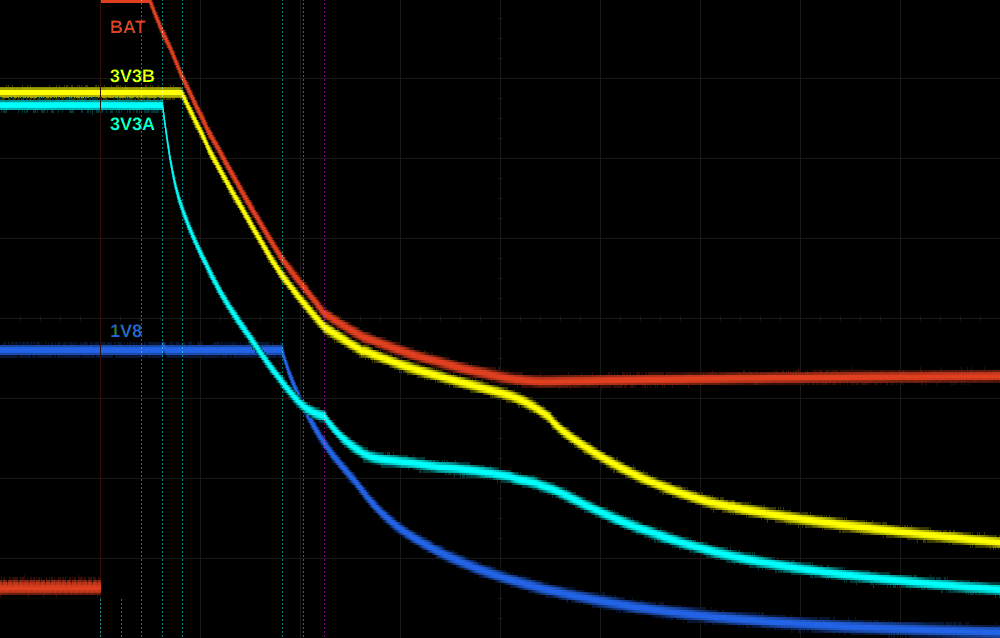
I’ve captured the shutdown sequence on DC versus BAT power in more detail by zooming in, omitting the 5V rails, and including the 3V3A. This is with no external hardware connected to the BBB other than the power supply and measurement probes:


Since location of jumps/bends in the signals made me suspicious about the location of some strobes, I also measured LDOs 1 and 2 (not included here to avoid clutter). It turned out strobe 15 follows strobe 1 on shutdown, in contradiction of figure 5 of the TPS datasheet. Given the bend in 3V3A around strobe 15 it also seems that some leakage from one of the LDO1 supplies (vrtc, vio, vdds) to 3V3A is also happening? That would be rather weird and unexpected (not to mention highly undesirable), so maybe I’m misreading this or it’s just a coincidence.
In the BAT-supply case, the current measured through BAT after shutdown is around 35 mA (somewhat dependent on temperature). I’ve analyzed the schematic and it appears there’s no specific culprit: there are many IO lines with pull-ups to 3v3b:
- 2× 4.75k for am335x boot mode (EMU0, EMU1)
- 11× 10k for eMMC
- 7× 10k for SD card
- 1× 10k for HDMI irq
- 4× 1.5k for ethernet (MDIO and phy mode select)
Since the total leakage is not huge and diffusely spread across dozens of processor IOs, and afaict no absolute maximum ratings are violated, it seems intuitively unlikely the cpu will get damaged this way. This will probably then also be true of the brief leakage currents occurring during boot and shutdown on DC power. (Not that I’m 100% sure about either)
Of course 35 mA @ 3.6V = 126 mW of power consumption is pretty bad, so even if the processor doesn’t get damaged it seems to me that people who run into this problem and are unable or unwilling to patch it in hardware should focus on deepsleep modes (which keep the PMIC in active-state) instead. Optimizing these will be hard work though.
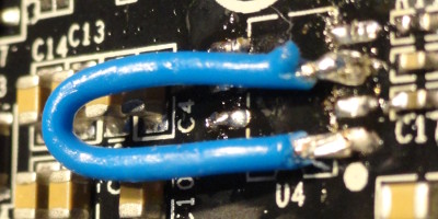
One thing one should however definitely never do, is leave a serial cable attached to a BAT-powered BBB whose 3v3b is stuck high. The uart buffer U15 is powered by 3v3b and directly drives the cpu UART0_RXD pin (even though ironically its intended purpose was to isolate the uart pins when the cpu is powered down). It has a pull-down on the associated input, but if you connect a serial cable it will be driven high instead. Here’s the result:


Lots of thoughts going on staring at those pictures: Much steeper slopes in the DC power case already indicate much higher currents. On battery power the 3V3A ends up a full volt higher than before, whoa, and wtf is that sudden surge on the 3V3A shortly after shutdown? Red warning lights start flashing in my head. Uhh, 3V3A is exceeding the 1.8V supplies by more than 2V there, a situation the am335x datasheet repeatedly and emphatically warns should be avoided under all circumstances.
Current through BAT (right before I quickly turned the PSU off) read 80 mA, 45 mA higher than before. Wait, does that mean this 45 mA flows through a single pin of the cpu? What’s the specified latch-up limit anyway? Looks it up… 45 mA. Uh oh…
So here we have a case where the situation was changed from “hmm, annoying power consumption” to “DANGER WILL ROBINSON, DANGER” by something as seemingly innocuous as attaching a serial cable to the console port.
In the DC-powered case everything is happening rather quickly and I have no idea how to estimate how big the risks are to the CPU, or whether cumulative damage may occur. At first glance it seems to avoid overvoltage stresses in this case (which I know are cumulative), and overcurrent situations are afaik mainly thermal in nature hence dependent on their duration. But even 1 ms may very well be an epic age to a processor like the am335x, I just have no idea.
In any case, the leakage currents occurring due to enabling 3v3b 1ms before 3v3a were sufficient motivation for a patch in BBB rev A6, so presumably they are not something to be ignored.
When CAPEs are attached, everything will depend on what exactly they are doing.
As far as hardware patches go, probably the most elegant solution would be to have the 3v3b (3v3exp in case of BBW) regulator actively track the 3v3a voltage rather than using it as enable-input. This avoids a problematic voltage difference under all circumstances, and all nets needed for this are already available at the site of the regulator, which simplifies things. (If the gods are in a very generous mood, perhaps there’s even some pin-compatible chip that does it… yeah right, just dreaming here.)
It would also allow the 3v3b to take advantage of the better calibration the 3v3a voltage seems to have, and the ability to adjust it at runtime for fine-tuning. In my pictures the 3v3b is evidently set slightly too high, and as a result gets poorly regulated on 3.6V supply.
The next best thing would be using a proper enable-signal occurring somewhere in the power sequence after the 3V3A but no later than PMIC_PGOOD (= am335x PORz). The PGOOD signal itself still seems like the best choice, unless some CAPE ends up unintentially pulling down SYSBOOT pins as a result (though iirc the cpu samples sysboot some time after PORz goes high, but this would need to be verified).
Using an enable-signal asserted before and/or deasserted after the 3V3A (such as LDO2 feeding the power led) is suboptimal but may work adequately. I’d still especially try to avoid strongly driving cpu pins during boot or shutdown (as happens on the BBB when console rxd is high), since that would leave me worried about the cpu’s long-term health.
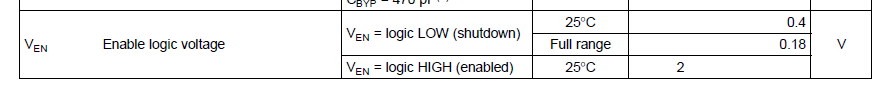
If one plans some ugly hack to make working enable-signal out of the 3V3A itself using voltage dividers or such, keep in mind it will still shut off later than desirable (3V3A only needs to drop 0.3V below 3V3B for leakage to start occurring) and the regulator isn’t guaranteed to shut off unless EN drops below:
- 0.50 V (BBW regulator)
- 0.40 V (BBB regulator, 25 ͏°C)
- 0.18 V (BBB regulator, whole temperature range)
Anyhow, I’m inclined to declare this issue “fully clarified” now, or at least I’ve done all investigation I’m probably going to. To those suffering from this issue I’d advise carefully reading this thread (or at least this branch thereof) and weighing the pros and cons of the various workarounds suggested, since the most suitable one will depend the individual situation.
Good luck to everyone!
Matthijs