Looking for a wiring diagram for the 4-20ma on the beagle bone black coms cape
Thanks I have that. It doesn’t detail the 4-20mA circut, unless I’m missing something. I’m trying to understand where power comes from and at what voltage.
Each of those two connectors are connected to an adc pin.
They both have a pull-down..
The ADC's can only take 1.8V, any more and they will fry..
Regards,
So the pull down is to keep the voltage under 1.8 correct? My confusion is I have one screw per input, 4-20mA is two wire where is the other half of the circut?
I think you have to provide an external voltage source - the 4-20 mA circuits are sort of like the Sink-A and Sink-B circuits, they are just one end of something.
I connect my 4-20 mA pressure gauges to the same 24V source that supplies my power cape. Then the return path from the pressure gauge goes through the shunt resistor across the analog input. However, I’m not using this cape, I built my own shunt circuit on a protoboard.
I tried 24- to gnd 24+ to sensor and - return from the sensor to AI5 same way I would connect a typical loop powered 4-20mA circuit. With the circuit connected to AI5 I get a reading but after a few seconds I also get a reading on AI6 close to the reading on AI5. If I remove the wire from AI5, AI5 imeadiatly drops to zero AI6 will stay elevated for a minute or more. If I connect to AI6 I get 0 on AI5 and AI6. Any ideas
I suspect the pull-down is only ensuring that the floating voltage is
tied to 0V; feeding anything with a voltage over 1.8V will still fry the
input. And since 0V likely also means 0mA, it indicates a fault condition
in the loop.
https://www.fluke.com/en-us/learn/best-practices/test-tools-basics/process-tools/what-is-a-4-20-ma-current-loop
https://www.predig.com/indicatorpage/back-basics-fundamentals-4-20-ma-current-loops
{Many others|
The input to the BBB likely needs to consist of a current->voltage
tranform, so the ADC can measure the voltage corresponding to the current.
Which might be built-into the cape (I've not looked at it).
Can anyone tell me how to connect a sensor to the 4-20mA input on the comms board.I need temperature and all 4-20mA temperature sensors I’m familiar with are 24 VDC not 1.8
you can use an current to voltage converter then an opamp to level shift it
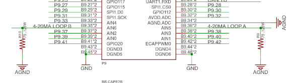
The comms board 4-20mA current loop input consists of a 75Ω shunt resistor across one of the analog input pins.
You need to connect an appropriate voltage source to your device and the other end of your device to the comms board input. Connect the ground of your voltage source to the Analog Ground pin.
Divide the measured voltage by 75 to obtain the current.
The cape does not provide a voltage source, Many devices use 24V excitation, but this is not universal. Thus the choice of voltage source is left to you.
Hope this helps someone. Schematic can be found here if you have any doubts: https://github.com/beagleboard/capes/blob/master/beaglebone/Comms/Comms_Cape_sch.pdf
Steve
Thanks that helps a lot, but the agnd is not actually brought out to the terminal strip only the gnd. How do I attach to agnd?
Dwayne:
Interesting question - I built my own shunt circuits on a protoboard so I was able to bring out a connection to P9_34.
After looking at the BBB schematic, I see there is a ferrite bead connecting GNDA to GND, so there is continuity between them and you should be able to use the GND on positions 1 or 10 of X1.
-Steve