-
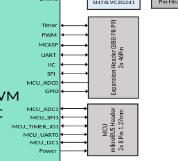
Is it possible to read analog voltage using P9 header pins and analog pin of MikroBUS header simultaneously (I want to 7 analog voltages using 7 ADC channels of P9 header and 1 analog voltage with MikroBUS header)?
-
How to read analog voltage from the analog pin of the MikroBUS header using Python code?
Bad news is I highly doubt the pin mux will have access to a/d on that many pins.
That mikroBUS really ruined that board due to lack of open access. If they have an a/d board you will have to use that. It will use i2C or you can connect any a/d with i2c on that header.
You should reach out the microBUS and see what they have for a solution, they make the plug in boards, it is upto mikroBUS to create the device tree/driver/specific code examples.
Another solution that does not have any python that I am aware of is to use an USB to a/d convertor.
Also, I should have asked first, what board are you running? beagleplay? Since you mentioned microBUS it was assumed BP board.
The board is BeagleBone AI-64. Sorry I should have stated it earlier. I was thinking whether I can use all the ADC channels of P9 header and the analog pin of MikroBUS header of BeagleBone AI-64 simultaneously or not? @foxsquirrel

Based upon the schematic it appears they are separate lines, so yes you could use them. You might have to make your own overlay or not. You will have to poke around a little bit and see what is running. Worst case you might have to make a overlay for that to be turned on.