I am looking to control three SSR’s (datasheet). I have tried directly hooking them up to the BB, but only one of them will actually switch when the GPIO pin is set to high. The datasheet says the trigger current is 7.5mA / 12 V (max 3-32V). I obviously need to augment the voltage and/or current, so I ordered a ULN2003. This is spec’d to do a max 500mA current (per driver) and 50V. I have tried to get a little basic understanding of the darlington array, but I can’t figure out a few things:
- For these SSRs’ input voltage, I can’t go over 32V. Does the input voltage on the ULN2003 match the output voltage?
- If I were able to use the BB’s 3.3V pin as the input voltage, would there be enough current to trigger the SSR?
- How many channels on the ULN could I power if I used the 3.3V on the BB? As I understand, the GPIO are not for sourcing current.
Another option (what makes the most sense to me) is using the BB’s 5V power supply for both the BB and the ULN2003. I don’t know where that puts the output voltage (question #1). The BBB docs suggest 2A supply if you are running a USB peripheral. I have a WiFi USB dongle being used. The supply is rated at 2A. According to my Kill-a-watt, I don’t see a draw of over 100mA. It draws 70-80mA at idle/load. I’m not sure if you can use the kill-a-watt as the amperage draw though?
Thanks
My reading of the datasheet is that the trigger current is the load current required to trip the zero crossing detector logic in order to turn on the load. I think it is separate from the input voltage required to activate the zero crossing detection circuitry.
In any case using a buffer like the ULN2003 to isolate the BBB GPIO pin from the SSR is a good idea.
Also, the current measured by your Kill-a-Watt is the 120 VAC input current draw by the power supply. It should produce 5 VDC at up to 2A on its output which is used to power the BBB.
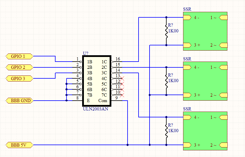
I would connect the GPIO pin to the input of the ULN2003 channel you are using (and remember to connect the unused inputs and the ground pin (pin 8) to the BBB GND). When the GPIO pin goes high (3.3 V) the ULN2003 input will draw about 1 mA from the GPIO pin. In turn the ULN2003 will turn on and its output will go low (to about 1 V above GND). This output should be connected to pin 4 of the SSR (as shown in the Application Hints section of the datasheet). Pin 3 of the SSR should be connected to the 5 V supply pin on the BBB. The ULN2003 will draw current current through the SSR input and the SSR should turn on after the next zero crossing. When the GPIO pin goes low (0 V) the ULN2003 will turn off and the SSR should turn off after the next zero crossing. To unsure the SSR turns off when the ULN2003 turns off you should connect a 1K pull-up resistor between the SSR pins 3 and 4. This resistor will draw about 4 mA when the ULN2003 is on. Finally, to ensure the ULN2003 is not destroyed by any inductive flyback (unlikely here, but possible), you should connect the COM pin (pin 9) to the BBB 5 V supply.
This will provide about 4 V on the input to turn it on (when the GPIO pin is high), and 0 V on the input to turn it off (when the GPIO pin is low). These values are greater than the min ON voltage (>2.4 V) and less than the max off voltage (<1 V) specified for the SSR.
I hope that is clear, a simple schematic would be better.
HTH
Dennis Cote
I tried to attach or insert a file, but in both cases I get a large empty rectangle on my screen and nothing else happens. I have to reload the webpage to get out of this state. Is there a secret to attaching a file?
Thanks.
Dennis Cote
File attaching started working after updating to latest Chrome (and therefore restarting Chrome).
Schematic is attached.
Dennis Cote
Thank you for the fantastic explanation. I haven’t gotten a chance to give it a try yet, but will let you know