On the ARM/Linux side, I am using the following code to read the ADC. This snippet isn’t exactly like the PRU code since it only reads one channel. When running the PRU code, I don’t disable the kernel driver for the TSCADC. I never have and we haven’t had any problems. How do I do that and I’ll try it if it makes a difference.
I have not tried adjusting the open delay, etc. As I said, it’s always worked fine for over a year.
else if (x == 14)
	      {

	      	printf("\nSingle channel detector.");
	      	// define file handle to read analog input

		    FILE* fAIN_0 = fopen("/sys/bus/iio/devices/iio:device0/in_voltage0_raw", "r");

		    while(KeepGoing)
		    {

		       fread(&AIN_0_str, 6, 1, fAIN_0);

		        rewind(fAIN_0);

		        AIN_0_fl = atof(AIN_0_str);


		      mvolts_AIN_0 = AIN_0_fl/4096*1.8;

		      if (x == 1)
		      {
		    	printf("Sensor output 0 is %.1f V + (Toggle the on/off switch to stop.)\n",mvolts_AIN_0);

		    	x = 0;
		      }
		      else
		      {
		    	printf("Sensor output 0 is %.1f V x (Toggle the on/off switch to stop.)\n",mvolts_AIN_0);

		        x = 1;
		      }
		      fread(&value_str, 6, 1, RunStopButton_val);
		      rewind(RunStopButton_val);

		      if (value_str[0] == '0')
		        {
		          printf("Stopping on switch interrupt");
		          KeepGoing = 0;
		        }
		      usleep(200000);
		    }
		    fclose(RunStopButton_val);

    		rewind (fAIN_0);

    		fclose(fAIN_0);

	      }
We read three channels with the PRU code. Here’s the C code for the PRU that sets up the ADC. This has worked on our test platform and in the lab for months.
static void ADCConfigure(void)
{
	unsigned int i, count, data;

	/* Enable ADC module clock */
	HWREG(SOC_CM_WKUP_REGS + CM_WKUP_ADC_TSC_CLKCTRL) = 0x02;

	/* Disable ADC module for configuration */
	HWREG(SOC_ADC_TSC_0_REGS + TSC_ADC_SS_CTRL) &= ~0x01;

	/* fs = 24MHz / ((CLKDIV+1)*2*Channels*(OpenDly+Average*(14+SampleDly)))
	 *    = 53.57kHz
	 * CLKDIV = 0
	 * Channels = 1
	 * Average = 16
	 * OpenDly = 0
	 * SampleDly = 0
	 */
	HWREG(SOC_ADC_TSC_0_REGS + TSC_ADC_SS_ADC_CLKDIV) = 0;

	HWREG(SOC_ADC_TSC_0_REGS + TSC_ADC_SS_ADCRANGE) = 0xFFF << 16;

	/* Disable all steps for now */
	HWREG(SOC_ADC_TSC_0_REGS + TSC_ADC_SS_STEPENABLE) &= 0xFF;

	/* Unlock step configuration */
	HWREG(SOC_ADC_TSC_0_REGS + TSC_ADC_SS_CTRL) |= 0x04;

	// Step 1 config: SW mode, one shot mode, fifo 0, channel 0, AIN0 on the Beaglebone Black, 4 samples averaged
	HWREG(SOC_ADC_TSC_0_REGS + TSC_ADC_SS_STEPCONFIG(0)) = 0x00000008;
	// Step 2 config: SW mode, one shot mode, fifo 0, channel 4, AIN4 on the Beaglebone Black, 4 samples averaged
	HWREG(SOC_ADC_TSC_0_REGS + TSC_ADC_SS_STEPCONFIG(1)) = 0x00200008;
	// Step 3 config: SW mode, one shot mode, fifo 0, channel 5, AIN5 on the Beaglebone Black, 4 samples averaged
	HWREG(SOC_ADC_TSC_0_REGS + TSC_ADC_SS_STEPCONFIG(2)) = 0x00280008;

	HWREG(SOC_ADC_TSC_0_REGS + TSC_ADC_SS_STEPDELAY(0)) = 0xFF000000;
	HWREG(SOC_ADC_TSC_0_REGS + TSC_ADC_SS_STEPDELAY(1)) = 0xFF000000;
	HWREG(SOC_ADC_TSC_0_REGS + TSC_ADC_SS_STEPDELAY(2)) = 0xFF000000;

	/* Enable channel ID tag */
	HWREG(SOC_ADC_TSC_0_REGS + TSC_ADC_SS_CTRL) |= 0x02;

	/* Clear end-of-sequence interrupt */
	HWREG(SOC_ADC_TSC_0_REGS + TSC_ADC_SS_IRQSTATUS) = 0x02;

	/* Enable end-of-sequence interrupt */
	HWREG(SOC_ADC_TSC_0_REGS + TSC_ADC_SS_IRQENABLE_SET) = 0x02;

	/* Lock step configuration */
	HWREG(SOC_ADC_TSC_0_REGS + TSC_ADC_SS_CTRL) &= ~0x04;

	/* Empty FIFO 0 */
	count = HWREG(SOC_ADC_TSC_0_REGS + TSC_ADC_SS_FIFOCOUNT(0));
	for (i = 0; i < count; i++) {
		data = HWREG(SOC_ADC_TSC_0_REGS + TSC_ADC_SS_FIFODATA(0));
	}

	/* Enable ADC module */
	HWREG(SOC_ADC_TSC_0_REGS + TSC_ADC_SS_CTRL) |= 0x01;
}
This is the code that actually reads the values from the ADC. Note - this was a handy copy and doesn’t do anything with the values read from channels 4 & 5.
	// Start step
	HWREG(SOC_ADC_TSC_0_REGS + TSC_ADC_SS_STEPENABLE) = 0xE; // enables steps 1,2 and 3.  TSC Charge is not enabled (bit 0)

	// Wait for interrupt
	while (!(HWREG(SOC_ADC_TSC_0_REGS + TSC_ADC_SS_IRQSTATUS)&0x02));

	// Clear interrupt
	HWREG(SOC_ADC_TSC_0_REGS + TSC_ADC_SS_IRQSTATUS) = 0x02;

	Data = 0xFFFFFFFF;

	count = HWREG(SOC_ADC_TSC_0_REGS + TSC_ADC_SS_FIFOCOUNT(0));


// #PRAGMA MUST_ITERATE
	for (i = 0; i < count; i++)	// count is the number of readings 								// in the ADC FIFO buffer
		{
			Data = HWREG(SOC_ADC_TSC_0_REGS + TSC_ADC_SS_FIFODATA(0));
			StepRead = (Data >> 16) & 0xF;
			RawAnalog = Data & 0xFFF;

			switch (StepRead)
				{

					case 0:
						Voltage = RawAnalog;
						break;
					case 1:
						break;
					case 2:
						break;
					default:
						break;
				}
}
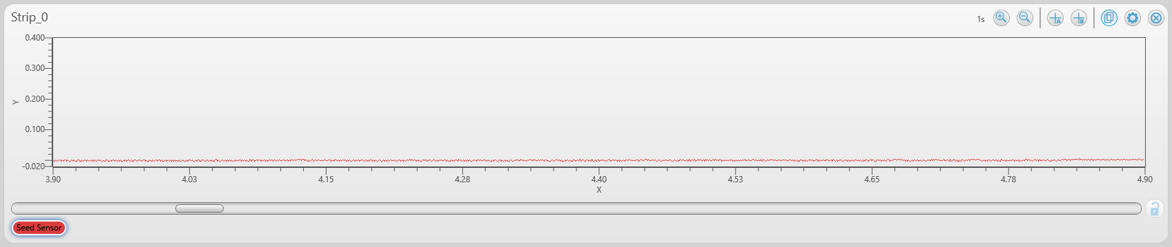
Here’s a snapshot from the DAQami software showing the signal as measured by the USB1408-FS. The first strip was captured while operating the system with the ARM/Linux C code HWTest.c.
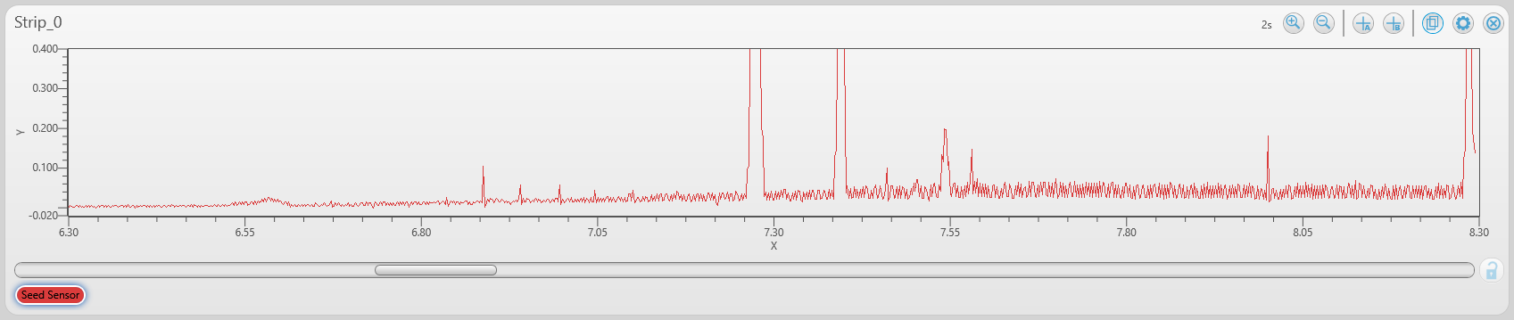
The second strip was captured while running the PRU code. Do you see how the signal drifts up on the strip captured while operating the system with the PRU code? Puzzling. We don’t change anything else between the two methods.