NO PINS ARE TO BE DRIVEN UNTIL AFTER THE SYS_RESET LINE GOES HIGH. DO NOT APPLY VOLTAGE TO ANY I/O PIN WHEN POWER IS NOT SUPPLIED TO THE BOARD. IT WILL DAMAGE THE PROCESSOR AND VOID THE WARRANTY.
So how to wire up a simple switch ?
i did not find the SYS_RESET Line mentioned anywhere else in the header-pinouts.
the only ones that are similar in naming are VOUT_VSYS and nRESET - there is no explanaiton on this site what exactly the pins are doing.. VOUT_VSYS is not searchable as in the table it is then written as VOUT - VSYS that is very confusing.
a text search for RESET does only bring up the warning-boxes and the nRESET pin.
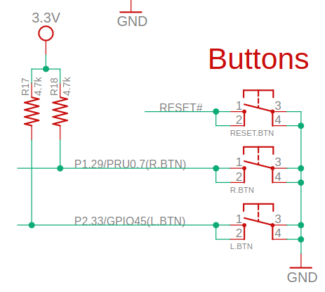
i then have looked up the TechLab schematics
and there the buttons are just wired to the 3.3V rail
No the TechLab is fine here, as 3v3 is powering the both the TechLab and the PB2..
The issue is when the PB2 (or any BeagleBoard.org) device is in an un-powered state (so Vcc = GND), and you supply a voltage signal (or potential) to any of the I/O, it will blow the internal I/O and destroy the part. After 3v3 and sys_reset trigger the PB2’s I/O is in a more protective state.
The copied BBB warning is pretty misleading here, especially with no matching SYS_RESET on the header. The powered-off case is the bit that tends to bite, not the button wiring itself.