Hi!
I’m trying to read temp with a ds18b20 sensor. I try with a few tutorial without luck.
Any tips for read this sensor?
I’m using Debian 8.6 2016-11-06 4GB SD SeeedStudio IoT (kernel 4.4.30-ti-r64)
regards,
Sebastián
Hi!
I’m trying to read temp with a ds18b20 sensor. I try with a few tutorial without luck.
Any tips for read this sensor?
I’m using Debian 8.6 2016-11-06 4GB SD SeeedStudio IoT (kernel 4.4.30-ti-r64)
regards,
Sebastián
I also am having no luck. I created an overlay:
root@beaglebone:~# cat w1-p9-13.dts
/dts-v1/;
/plugin/;
/ {
compatible = “ti,beaglebone”, “ti,beaglebone-black”, “ti,beaglebone-green”;
part-number = “BB-W1”;
version = “00A0”;
/* state the resources this cape uses /
exclusive-use =
/ the pin header uses /
“P9.13”,
/ the hardware IP uses */
“gpio0_31”;
fragment@0 {
target = <&am33xx_pinmux>;
overlay {
dallas_w1_pins: pinmux_dallas_w1_pins {
pinctrl-single,pins = < 0x74 0x37 >;
};
};
};
fragment@1 {
target = <&ocp>;
overlay {
onewire@0 {
compatible = “w1-gpio”;
pinctrl-names = “default”;
pinctrl-0 = <&dallas_w1_pins>;
status = “okay”;
gpios = <&gpio1 31 0>;
};
};
};
};
Compiled and then copied it to /lib/firmware as BB-W1-P9-13-00A0.dtbo. Did echo BB-W1-P9-13 > /sys/devices/platform/bone_capemgr/slots.
root@beaglebone:~# cat /sys/devices/platform/bone_capemgr/slots
0: PF---- -1
1: PF---- -1
2: PF---- -1
3: PF---- -1
4: P-O-L- 0 Override Board Name,00A0,Override Manuf,BB-W1-P9-13
tail of dmesg shows:
[ 221.082070] bone_capemgr bone_capemgr: slot #6: ‘Override Board Name,00A0,Override Manuf,BB-W1-P9-13’
[ 221.108759] bone_capemgr bone_capemgr: slot #6: dtbo ‘BB-W1-P9-13-00A0.dtbo’ loaded; overlay id #0
[ 223.111781] w1_master_driver w1_bus_master1: w1_search: max_slave_count 64 reached, will continue next search.
There is no activity on the oscilloscope for that pin.
root@beaglebone:~# ls /sys/devices/w1_bus_master1/
00-400000000000 w1_master_add w1_master_remove
00-800000000000 w1_master_attempts w1_master_search
driver w1_master_max_slave_count w1_master_slave_count
power w1_master_name w1_master_slaves
subsystem w1_master_pointer w1_master_timeout
uevent w1_master_pullup w1_master_timeout_us
Have tried other overlays on different pins. No luck. The sensor is good, since I checked it out on a WiPy V2.0 board.
Am frustrated by this.
Board info:
root@beaglebone:~# uname -a
Linux beaglebone 4.4.29-bone-rt-r14 #1 PREEMPT RT Tue Nov 1 21:30:09 UTC 2016 armv7l GNU/Linux
In all of the examples that I have seen, the P9.x → GPIO bank.port translates to GPIO (bank +1).port between lines in the overlay script.
That's incorrect if I understand what you're trying to say. the P8/P9
header values for the pins have absolutely no correlation to the kernel pin
values. These values can be gleaned from the schematics. But I typically
use something like the attached file( in pdf format ) that lists all the
important data I need.
For example P9.22 has a kernel gpio value of gpio0_2. What this means is
that the pin is on gpio bank0 ( bank zero ), and is pin 2 of that gpio
bank. Note, that on the beaglebone there are 4 GPIO banks. gpio0-gpio3. Now
with this in mind. to figure out the sysfs gpio number you would . ..
gpio_bank * 32 + pin number. So, for the sysfs file entry for the P9.22
pin. Our pin would be gpio2. But for example, and arguments sake. If this
pin were on gpio_bank 1, then the sysfs entry for this pin would be gpio34.
gpio_bank 1 * 32 + 2.
Irregardless, I just gave you a step by step, exact steps recipe to
success. That I wrote as I figured it out for the first time myself.
Ah forgot the screenshot . . .
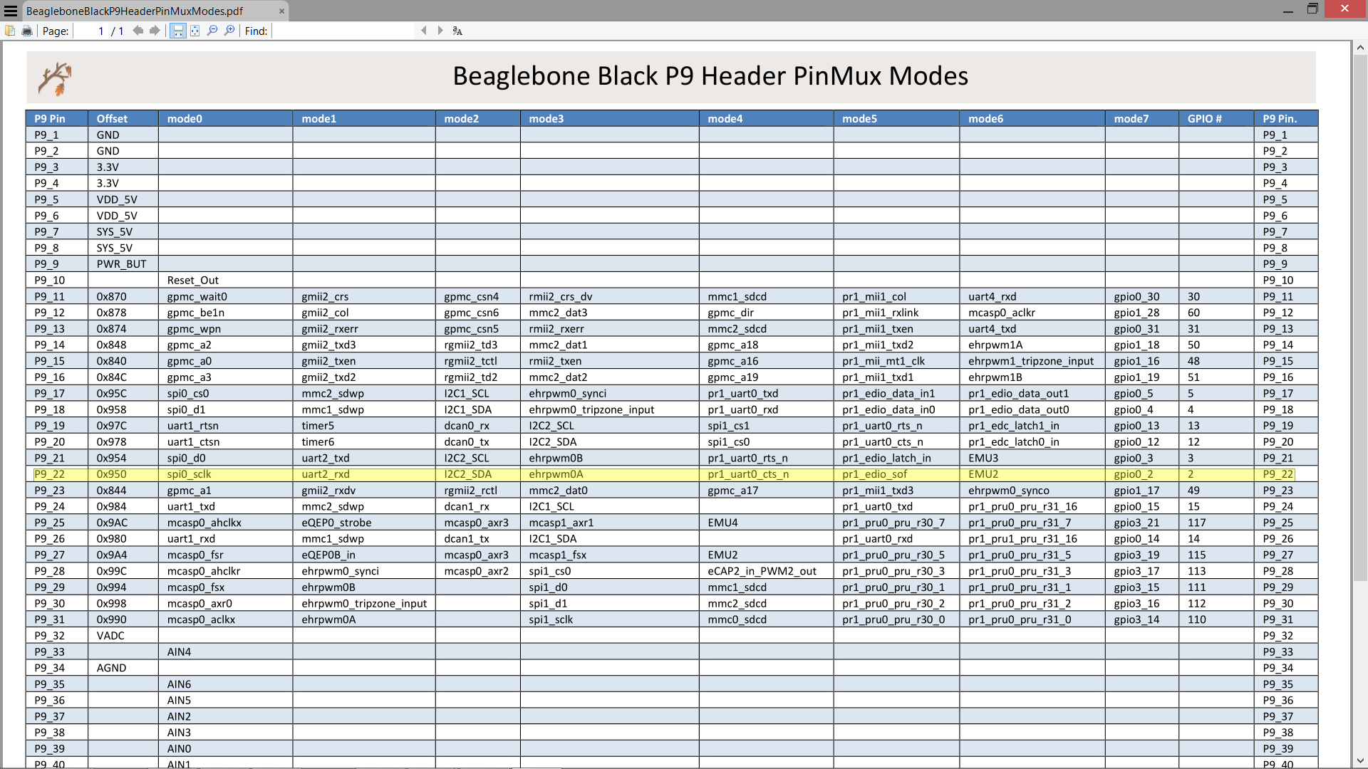
Note the “mode7” column to the far right.
@Sebastián Sáez
Perhaps you’re ready to test the libpruw1 project:
pinmuxing handled by libpruio → single source, just choose the bus pin in your source code (no device tree magic necessary)
transparent bus input and output → broadcast triggering of multiple sensors, fast readings
monitoring feature → watch what’s going on at the bus @ 1MHz sampling rate (find interferences, sensor failures, …)
Find example source code at this link.
Regards
thanks TJF for the tips 
Thanks William. I’ll try out your instructions on Mon.
One thing I did not mention last night was that I did all this one a
beaglebone black running . . .
william@beaglebone:~$ cat /etc/dogtag
BeagleBoard.org Debian Image 2016-10-30
william@beaglebone:~$ uname -r
4.4.27-ti-r62
So, someone mentioned in the last couple of days ( I think ) that they're
using a 3.8.x kernel. A couple of concerns with this is that a) the
overlays as described by me may not work the same. Meaning, I do not recall
if 3.8.x overlays are slightly different or not. Through the source, or in
how dtc compiles the source into "binaries". b) The sysfs file entries are
possibly going to be different.
Honestly, I could not say for sure, because last night was the very first
time I've setup 1-wire on the beaglebone. I just know / knew how to modify
the overlay's source in order for it to be proper. How to wire up the
sensor through a buddy of mine( someone with 35+ years electronics design
experience ). Here, see everyone on the web is saying to run a 4.7k
resistor between Vdd, and DQ on the sensor. Even if you're externally
powering the sensor. Where I've been told this is not necessary, and that
the resistor is only needed if you're going to parasitically power the
sensor through the DQ pin. Which my buddy does not seem convinced that this
sensor can be powered through a Beaglebone GPIO. So "erroring" on the side
of caution least I burn out a GPIO pin, or worse yet the processor. I opted
to power via an external power source. Also reading the datasheet I noticed
the input voltage range for the sensor is something like 2v8 to 5v6 ish . .
. I just powered the sensor straight off P9.5( 5v ). Indeed, in the end, it
seems to work perfectly fine this way. But I did not double check the temp
output to make sure it was accurate. I am however reasonably convinced it's
fine. I'll double check later with another kind of temperature sensor that
I know is accurate within a degree or two. Close enough for me . . . we
even have some K-type thermocouplers here( MAX31855 ) that are very
accurate if it ever comes to that. I haven't done SPI on the beaglebone yet
though . . . Anyway . . .
The image I'm using is the one Robert says is the latest Jessie "release"
image that will be shipping with the BBGW's soon( I believe ). Everything
else as far as I can remember is pretty stock. Except I've installed a few
Debian packages that should have no bearing on this subject at all (
build-essential, git, nfs-client. acpid, maybe i2c-tools, etc ).
Wait, one thing I did change in /boot/uEnv.txt:
##BeagleBone Black: HDMI (Audio/Video) disabled:
dtb=am335x-boneblack-emmc-overlay.dtb
I do not think this overlay is loaded by default on the stock image. For
the pin I chose, I do no think it's related to hdmi at all. But if you're
going ot use a different pin, you should double check to make the pin does
not conflict with the hdmi pins. Or some other board function. Picking
I2C0, or I2C2 pins would also not work out very good. As well as the eMMC
pins, if you're running off the eMMC . . . standard double check everything.
By the way, for informational purposes. The board file I’m loading( am335x-boneblack-emmc-overlay.dtb ) for my BBB should also work with BBG’s too. At least I’ve used it with several Greens, and have had zero problems with it. Now, when I say “several” think in the range of 40-50 different boards . . .
Sebastián,
I do not know what to say. You possibly have a pin conflict in one of your overlays somewhere. I’d check through all the source file for the dtbo’s you’re using, and make sure there are no P9.22 references in an of them. Except the 1-wire overlay file.
Again, thanks Williams… that was it.
I commented everything about P9.22 in ./bb.org-overlays/src/arm/univ-bbgw-00A0.dts
Then build and install with your instruccions
Which is an elegant way to mount the w1 overlay automatically after reboot?
By the way, I switched my VCC to 3.3V
regards,Sebatián
Again, thanks Williams... that was it.
I commented everything about P9.22 in ./bb.org-overlays/src/arm/
univ-bbgw-00A0.dts
Then build and install with your instruccionsWhich is an elegant way to mount the w1 overlay automatically after reboot?
There are a few different ways. Pretty much you can google search for
"debian boot script", and find around 3 different ways, that I can think of
off the top of my head.
1. write a script that's called by rc.local
2. write a startup service, there are two ways to do this.
3. create a one time at boot cron job.
In my mind, using Debian Jessie, creating a systemd service is the correct
way to go about this. But in case that turns out to be too difficult, or
cumbersome for your needs. Technically LSB sysv type services are also
possible in Jessie. These are also rather hard to understand at first too.
So writing a script, and then calling it from rc.local is probably the
easiest way - Initially.
Cron jobs, in my mind are not really the right way to go. Because again,
in my mind, cron jobs are meant to run something repeatable. Meaning
running something multiple times. Once a day at a specific time, Once every
hour, minute, whatever you like. However, it is possible to run a cron job
once every reboot. . . .
I would however recommend that you read up on systemd services, and use
that method.
@ Sebastian
Ah I forgot to mention loading capes from /boot/uEnv.txt. So . . .
william@beaglebone:~$ cat /boot/uEnv.txt |grep cape
#cmdline=coherent_pool=1M quiet cape_universal=enable video=HDMI-A-1:1024x768@60e
#cape_disable=capemgr.disable_partno=
#cape_enable=capemgr.enable_partno=
#cape_disable=bone_capemgr.disable_partno=
cape_enable=capemgr.enable_partno=<overlay_name> is the way to go. You can assign multiple cape overlays with this feature, but I do not remember if they are space, or comma separated. I’m thinking comma separated, but may be wrong.
That’s the first step.
The second step would be to . . .
Copy all your required overlays into /lib/firmware, which you’ve probably already done.
william@beaglebone:~$ cd /opt/scripts/
william@beaglebone:/opt/scripts$ git pull
william@beaglebone:/opt/scripts$ cd tools/developers/
william@beaglebone:/opt/scripts/tools/developers$ sudo ./update_initrd.sh
What this does, is notes what’s in uEnv.txt in the way of enabled capes, then which overlays you have in /lib/firmware, and “injects” these overlays into the initramfs. This is important, and if not done, your overlays will not load at boot using this method. But the upside is that once done, this will load your overlays at boot faster than any other method. Near instantly at boot, 1-2 seconds tops.
Anyway, this method is fairly easy, and is actually the best way to go.
I repeated this process for P8.14, and it works fine. This is just to let others who may not be aware that you can use 1-wire on any gpio pin that is not already in use by the system. Again, double check the pins in the schematic, to make sure they’re not being used by somethign like HDMI( which you can disable hdmi audio and video if you do not need it. ), or i2c-0 / i2c-2, emmc, sdcard, etc. But again you have to of course change the overlay to reflect the pin you need to use.
william@beaglebone:~$ diff ./dev/bb.org-overlays/src/arm/BB-W1-P8.14-00A0.dts ./dev/bb.org-overlays/src/arm/BB-W1-P9.12-00A0.dts
1c1,2
< /*
OR P8.26 . . . *smacks hardware designer / buddy . . .
william@beaglebone:~/dev/bb.org-overlays$ diff src/arm/BB-W1-P8.26-00A0.dts src/arm/BB-W1-P8.14-00A0.dts
4c4
< * Virtual cape for onewire on connector pin P8.26