I just signed up, I would like recive your help to avoid damage I have to connect the BBB with the SN74174 and SN74175 integrated circuits.
The SN74174 chip reads a voltage of at least 2V as an high signal so there should be no problems to connect it directly to a GPIO of the BBB, it is correct?
Can I connect also the output pin of the SN74175 chip directly to a GPIO pin of the BBB or I have to use a resistive network to limit the voltage to 3.3V?
Can i power the two ICs from the 5V present on the P9_5 and P9_6 pins of the BBB?
I normally use the 74LVC line of chips if I need to drive anything at 5V with Beagles.
You need to be careful with anything 5V, because the GPIOs are not 5V tolerant.
Thanks for the answer, but in my haste I typed the code incorrectly
I know that the 74HCxxx series can work well at 3V3, but I have to connect SN75174 SN75175…
if you just driving the device, it should work. if the BBB is receiving input from the sn74, then maybe a voltage divider, as long as high speed is not an issue.
right idea,
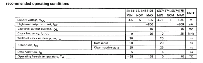
what is BBB gpio input high? with a typical of 3.4 Vout of sn75154, the resistors you choose will produce 2.0 volts input to BBB. sn75154 output load is about 400uA, which is 2x lower than max.
if BBB gpio Vin high is less than 2.0 volts, you should be good.
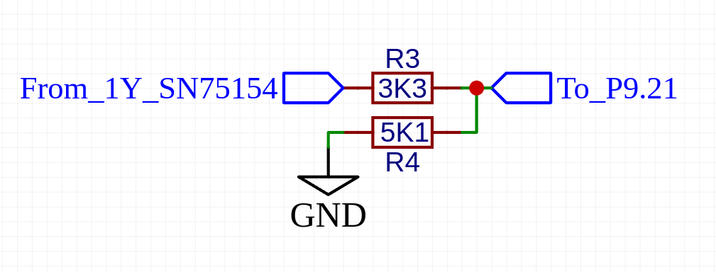
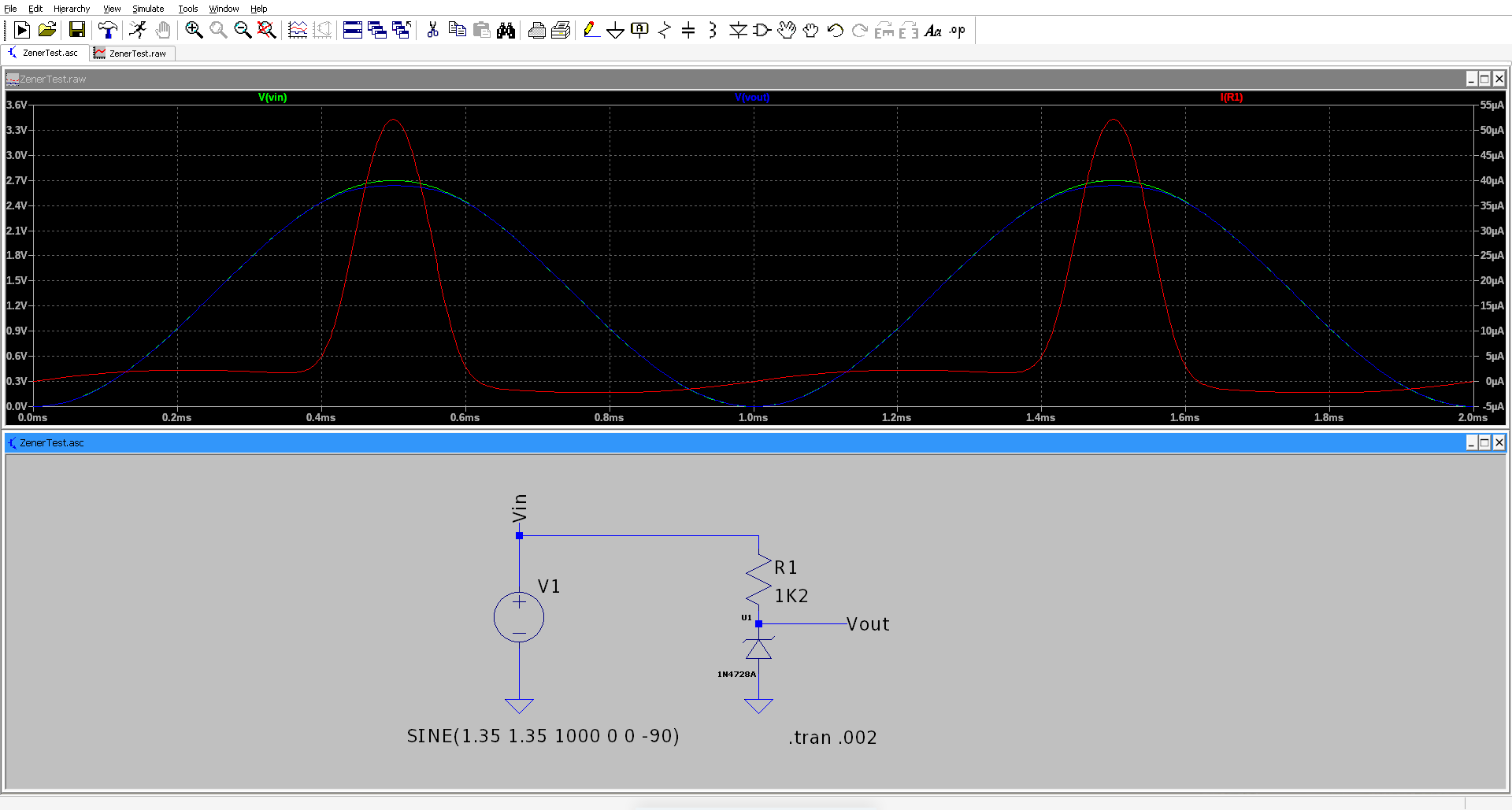
I believe the minimum voltage received as high by BBB is 2V, the minimum high-level output voltage of the SN75175 is 2.7V; in the worst condition with the resistors that I have chosen the voltage will 1.63V… I think it is best to change the R4 with a Zener diode of 3V, so as to always have a voltage higher than the minimum read as high; is it a good practice?
zener diodes tend to take mA to reach the zerner voltage. might just need to set things up and measure with a volt meter. (without connecting to the BBB)
The actual zener voltage depends on the current, so you should check the datasheet for the diode you’re using to ensure the voltage really is what you want.
In the static situation you’ve described above, I dont think theres much advantage using a zener diode.
Today I made the circuit on breadboard, used an ESP32 to create a square wave, from 16Hz to 750KHz the output of SN75175 oscillates from 0.3V to 2.6V @16Hz and from 0.5V to 2.3V @750KHz (I have used a resistive divider made with a resisor of 3.3K and one of 10K Ohm because at the output pin I have a voltage of about 3.55V at high level)
My old Philips oscilloscope is not really accurate but I think I have almost enough margin to stay safe