enable i2c1 and spi1 on beaglebone black using yocto scarthgap

Hello guys,

I have a beaglebone black and I am tying to enable the following:

  • i2c1 so it can work with a ISL1209 RTC , using pins P9_17 and P9_18

  • spi1 so it can work with a CY15B104QN FRAM, using pins P9_28, P9_29, P9_30, P9_31

I am trying to work with yocto scarthgap (with kirkstone it was ok - the i2c part - but something changed I suppose).

Here is my setup:

bblayers.conf

POKY_BBLAYERS_CONF_VERSION = "2"

BBPATH = "${TOPDIR}"
BBFILES ?= ""

BSPDIR := "${@os.path.abspath(os.path.dirname(d.getVar('FILE', True)) + '/../..')}"

BBLAYERS ?= " \
  ${BSPDIR}/poky/meta \
  ${BSPDIR}/poky/meta-poky \
  ${BSPDIR}/poky/meta-yocto-bsp \
  ${BSPDIR}/meta-ti/meta-ti-bsp \
  ${BSPDIR}/meta-ti/meta-ti-extras \
  ${BSPDIR}/meta-arago/meta-arago-demos \
  ${BSPDIR}/meta-arago/meta-arago-distro \
  ${BSPDIR}/meta-arago/meta-arago-extras \
  ${BSPDIR}/meta-arago/meta-arago-test \
  ${BSPDIR}/meta-openembedded/meta-oe \
  ${BSPDIR}/meta-openembedded/meta-multimedia \
  ${BSPDIR}/meta-openembedded/meta-networking \
  ${BSPDIR}/meta-openembedded/meta-python \
  ${BSPDIR}/meta-openembedded/meta-filesystems \
  ${BSPDIR}/meta-arm/meta-arm \
  ${BSPDIR}/meta-arm/meta-arm-bsp \
  ${BSPDIR}/meta-arm/meta-arm-toolchain \
  ${BSPDIR}/meta-arm/meta-arm-systemready \
  ${BSPDIR}/meta-qt5 \
  ${BSPDIR}/meta-custom \
  "

In my local.conf I’ve set MACHINE ?= "beaglebone-yocto"

My meta-custom has the following:
recipes-kernel/linux/linux-bb%.bbappend

PR = "r0"

FILESEXTRAPATHS:prepend := "${THISDIR}/files:"

SRC_URI:append = " \
    file://custom-config.cfg \
    file://enable_i2c1.dtsi \
    file://enable-spi-cy15.dtsi \
"

do_configure:append() {
    cp ${WORKDIR}/enable_i2c1.dtsi ${B}/source/arch/${ARCH}/boot/dts
    cp ${WORKDIR}/enable-spi-cy15.dtsi ${B}/source/arch/${ARCH}/boot/dts
    echo '#include "enable_i2c1.dtsi"' >> ${B}/source/arch/${ARCH}/boot/dts/am335x-boneblack.dts
    echo '#include "enable-spi-cy15.dtsi"' >> ${B}/source/arch/${ARCH}/boot/dts/am335x-boneblack.dts
}

do_compile:append() {
    # Ensure the custom .config file is used
    yes '' | make oldconfig
}

custom-config.cfg

CONFIG_EXPERT=y
CONFIG_CONFIGFS_FS=y
CONFIG_OVERLAY_FS=y
CONFIG_RFKILL_GPIO=y
CONFIG_MTD_SPI_NOR=y
CONFIG_MTD_SPI_NOR_USE_4K_SECTORS=y
CONFIG_MTD_SPI_NOR_SWP_DISABLE_ON_VOLATILE=y
CONFIG_OF_DYNAMIC=y
CONFIG_OF_RESOLVE=y
CONFIG_OF_OVERLAY=y
CONFIG_TOUCHSCREEN_ADS7846=n
CONFIG_RFKILL_INPUT=y
CONFIG_DEBUG_MEMORY_INIT=y
CONFIG_SPI_DEBUG=y
CONFIG_SPI=y
CONFIG_SPI_MASTER=y
CONFIG_SPI_MEM=y
CONFIG_SPI_MUX=y
CONFIG_SPI_SPIDEV=y
CONFIG_SPI_LOOPBACK_TEST=m
CONFIG_SPI_SLAVE=y
CONFIG_SPI_SLAVE_TIME=y
CONFIG_SPI_SLAVE_SYSTEM_CONTROL=y
CONFIG_SPI_DYNAMIC=y
CONFIG_PPS=y
CONFIG_GPIO_SYSFS=y
CONFIG_RTC_DRV_ISL1208=y
CONFIG_MULTIPLEXER=y
CONFIG_JFFS2_FS=y
CONFIG_JFFS2_FS_DEBUG=0
CONFIG_JFFS2_FS_WRITEBUFFER=y
CONFIG_JFFS2_ZLIB=y
CONFIG_JFFS2_RTIME=y
CONFIG_UBIFS_FS=y
CONFIG_UBIFS_FS_ADVANCED_COMPR=y
CONFIG_UBIFS_FS_LZO=y
CONFIG_UBIFS_FS_ZLIB=y
CONFIG_UBIFS_FS_ZSTD=y
CONFIG_UBIFS_ATIME_SUPPORT=y
CONFIG_UBIFS_FS_XATTR=y
CONFIG_UBIFS_FS_SECURITY=y
CONFIG_CRYPTO_LZO=y
CONFIG_CRYPTO_ZSTD=y

enable_i2c1.dtsi

&am33xx_pinmux {
                                                                                /* I2C-1: My i2c and muxing it for my needs */
        my_i2c1_pins: my_i2c1_pins {
                pinctrl-single,pins = <                                         /* My device: i2c addr 0x22, 0x23 */
                        AM33XX_IOPAD(0x95c, PIN_INPUT | MUX_MODE2)              /* (A16)/(Pin 50)  spi0_cs0.I2C1_SCL   */
                        AM33XX_IOPAD(0x958, PIN_INPUT | MUX_MODE2)              /* (B16)/(Pin 49)  spi0_d1.I2C1_SDA    */
                >;
        };
};

&i2c1 {                                                                         /* My i2c device 0x22, 0x23 */
        status = "okay";
        pinctrl-names = "default";
        pinctrl-0 = <&my_i2c1_pins>;

        clock-frequency = <100000>;


        rtc@6f {
                compatible = "isil,isl1208";
                reg = <0x6f>;
        };
};

enable-spi-cy15.dtsi

&am33xx_pinmux {
    my_spi1_pins: pinmux_my_spi1_pins {
        pinctrl-single,pins = <
                AM33XX_IOPAD(0x990, PIN_INPUT_PULLUP | MUX_MODE3) /* spi1_sclk */
                AM33XX_IOPAD(0x994, PIN_INPUT_PULLUP | MUX_MODE3) /* spi1_d0 */
                AM33XX_IOPAD(0x998, PIN_OUTPUT_PULLUP | MUX_MODE3) /* spi1_d1 */
                AM33XX_IOPAD(0x99C, PIN_OUTPUT_PULLUP | MUX_MODE3) /* spi1_cs0 */
        >;
    };
};

&spi1 {
    status = "okay";
    pinctrl-names = "default";
    pinctrl-0 = <&my_spi1_pins>;
    spi-max-frequency = <24000000>;

    spidev@0 {
        compatible = "spidev";
        reg = <0>;
        spi-max-frequency = <24000000>;
    };

    spidev@1 {
        compatible = "spidev";
        reg = <1>;
        spi-max-frequency = <24000000>;
    };
};

recipes-core/images/core-custom-beaglebone.bb

inherit core-image

# Include the core-image-minimal recipe
require recipes-core/images/core-image-minimal.bb

CORE_IMAGE_EXTRA_INSTALL += " kernel-modules"

IMAGE_INSTALL += " nano libgpiod"
IMAGE_INSTALL += " sysfsutils i2c-tools spitools config-pin"


IMAGE_INSTALL += " libgpiod-tools libgpiod-dev"

And now some outputs from the board:

root@beaglebone-yocto:~# dmesg | grep i2c
[    2.114915] i2c_dev: i2c /dev entries driver
[    2.229480] omap_i2c 4819c000.i2c: bus 2 rev0.11 at 100 kHz
[    2.266352] platform 4830e000.lcdc: Fixed dependency cycle(s) with /ocp/interconnect@44c00000/segment@200000/target-module@b000/i2c@0/tda19988@70
[    3.457405] omap_i2c 44e0b000.i2c: bus 0 rev0.11 at 400 kHz
root@beaglebone-yocto:~# dmesg | grep spi
root@beaglebone-yocto:~# i2cdetect -l
i2c-0	i2c       	OMAP I2C adapter                	I2C adapter
i2c-2	i2c       	OMAP I2C adapter                	I2C adapter
root@beaglebone-yocto:~# ls -l /dev/spi*
ls: cannot access '/dev/spi*': No such file or directory
root@beaglebone-yocto:~# cat /proc/mtd 
dev:    size   erasesize  name
root@beaglebone-yocto:~# uname -a 
Linux beaglebone-yocto 6.6.21-yocto-standard #1 PREEMPT Tue Mar 19 16:42:51 UTC 2024 armv7l GNU/Linux

I would really appreciate some help from you guys :slight_smile:

I have the BBB up on scarthgap, the walk-around looks good. Used the Ti recipe MACHINE=“beaglebone” so everything should work. I tried to load the device trees that are “official” and were installed along with rootfs, however they do not load. It has “ignoring unknown command” when extlinux.conf is opened up.

Update: found the issue why they did not load and fixed that and they load fine.

root@beaglebone:/sys/bus/spi/devices# ls
spi1.0	spi1.1

Yocto, scarthgap 6.1 kernel, MACHINE=“beaglebone”

I loaded both of the BBB overlays
BB-SPIDEV0-00A0.dtbo and BB-SPIDEV1-00A0.dtbo

in extlinux.conf ?
So you did not use the dtsi files that I’ve used? (see my recipes-kernel/linux/linux-bb%.bbappend )
From where did you get those dtbo files and how did you apply them?
Thanks for your time and support btw :smiley:

root@beaglebone:/boot/dtb# ls
AM335X-PRU-UIO-00A0.dtbo    BB-HDMI-TDA998x-00A0.dtbo	       BB-UART1-00A0.dtbo     PB-MIKROBUS-0.dtbo	       am335x-bonegreen-wireless-uboot-univ.dtb
BB-ADC-00A0.dtbo	    BB-I2C1-MCP7940X-00A0.dtbo	       BB-UART2-00A0.dtbo     PB-MIKROBUS-1.dtbo	       am335x-bonegreen-wireless.dtb
BB-BBBW-WL1835-00A0.dtbo    BB-I2C1-RTC-DS3231.dtbo	       BB-UART4-00A0.dtbo     am335x-bone.dtb		       am335x-bonegreen.dtb
BB-BBGG-WL1835-00A0.dtbo    BB-I2C1-RTC-PCF8563.dtbo	       BB-W1-P9.12-00A0.dtbo  am335x-boneblack-pps.dtb	       am335x-pocketbeagle.dtb
BB-BBGW-WL1835-00A0.dtbo    BB-I2C2-BME680.dtbo		       BBORG_COMMS-00A2.dtbo  am335x-boneblack-uboot-univ.dtb  am335x-sancloud-bbe-extended-wifi.dtb
BB-BONE-4D5R-01-00A1.dtbo   BB-I2C2-MPU6050.dtbo	       BBORG_FAN-A000.dtbo    am335x-boneblack-uboot.dtb       am335x-sancloud-bbe-lite.dtb
BB-BONE-LCD4-01-00A1.dtbo   BB-LCD-ADAFRUIT-24-SPI1-00A0.dtbo  BBORG_RELAY-00A2.dtbo  am335x-boneblack-wireless.dtb    am335x-sancloud-bbe.dtb
BB-BONE-NH7C-01-A0.dtbo     BB-NHDMI-TDA998x-00A0.dtbo	       BONE-ADC.dtbo	      am335x-boneblack.dtb
BB-BONE-eMMC1-01-00A0.dtbo  BB-SPIDEV0-00A0.dtbo	       M-BB-BBG-00A0.dtbo     am335x-boneblue.dtb
BB-CAPE-DISP-CT4-00A0.dtbo  BB-SPIDEV1-00A0.dtbo	       M-BB-BBGG-00A0.dtbo    am335x-bonegreen-gateway.dtb

If you don’t have those on the target use the TI recipe, MACHINE=“beaglebone”

Also remove some of the layers that are not being used and use this conf.

fred@eng-dev2:~/build1/ti/bbb-scarthgap$ bitbake-layers show-layers
NOTE: Starting bitbake server...
layer                 path                                                                    priority
========================================================================================================
core                  /home/fred/code/poky/meta                                               5
arm-toolchain         /home/fred/code/meta-arm/meta-arm-toolchain                             5
meta-arm              /home/fred/code/meta-arm/meta-arm                                       5
meta-ti-bsp           /home/fred/code/meta-ti/meta-ti-bsp                                     6
meta-ti-extras        /home/fred/code/meta-ti/meta-ti-extras                                  6
yoctobsp              /home/fred/code/poky/meta-yocto-bsp                                     5
yocto                 /home/fred/code/poky/meta-poky                                          5
openembedded-layer    /home/fred/code/meta-openembedded/meta-oe                               5
meta-python           /home/fred/code/meta-openembedded/meta-python                           5
networking-layer      /home/fred/code/meta-openembedded/meta-networking                       5
meta-arm-bsp          /home/fred/code/meta-arm/meta-arm-bsp                                   5

This will be your extlinux.conf, you will have to modify it on the SD card from the host or mount the other partition on the target. Simpler to update on the host.

# Generic Distro Configuration file generated by OpenEmbedded
LABEL Poky (Yocto Project Reference Distro)
	KERNEL ../zImage
	FDT ../am335x-boneblack.dtb
	FDTOVERLAYS ../BB-UART2-00A0.dtbo ../BBORG_RELAY-00A2.dtbo ../BB-SPIDEV0-00A0.dtbo ../BB-SPIDEV1-00A0.dtbo
	APPEND root=PARTUUID=${uuid} rootwait rw earlycon console=${console},${baudrate}

I’ve removed now all the extra layers and the images that were generated were only .wic.bmap and .wic.xz (and no .wic) but that wouldn’t be a problem since I can use bmaptool to write the card.

BUT… here is what the problem is:

[    4.850682] /dev/root: Can't open blockdev
[    4.855057] VFS: Cannot open root device "PARTUUID=" or unknown-block(0,0): error -6
[    4.863131] Please append a correct "root=" boot option; here are the available partitions:
[    4.871828] Kernel panic - not syncing: VFS: Unable to mount root fs on unknown-block(0,0)
[...]
[    4.936021] Exception stack(0xe0009fb0 to 0xe0009ff8)
[    4.941101] 9fa0:                                     00000000 00000000 00000000 00000000
[    4.949319] 9fc0: 00000000 00000000 00000000 00000000 00000000 00000000 00000000 00000000
[    4.957535] 9fe0: 00000000 00000000 00000000 00000000 00000013 00000000
[    4.964199] ---[ end Kernel panic - not syncing: VFS: Unable to mount root fs on unknown-block(0,0) ]---

I cleaned all now and rebuild. maybe I missed something.

EDIT: Something is wrong here… I have to manually get the PARTUUID (mount the card on my host and blkid )of the root partition and place it in the extlinux.conf

ok, so it seems that I can see some deviced under:

root@beaglebone:~# ls -l /dev/spi*
crw------- 1 root root 153, 1 Jan  1  1970 /dev/spidev1.0
crw------- 1 root root 153, 0 Jan  1  1970 /dev/spidev1.1

But when I try to communicate with my CY15B104QN FRAM there is no response from it whatsoever:

root@beaglebone:~# spidev_test -D /dev/spidev1.0 -p "\x06" -v
spi mode: 0x0
bits per word: 8
max speed: 500000 Hz (500 kHz)
TX | 06 __ __ __ __ __ __ __ __ __ __ __ __ __ __ __ __ __ __ __ __ __ __ __ __ __ __ __ __ __ __ __  |.|
RX | 00 __ __ __ __ __ __ __ __ __ __ __ __ __ __ __ __ __ __ __ __ __ __ __ __ __ __ __ __ __ __ __  |.|
root@beaglebone:~# spidev_test -D /dev/spidev1.0 -p "\x02\x00\x00\x00\xAA" -v
spi mode: 0x0
bits per word: 8
max speed: 500000 Hz (500 kHz)
TX | 02 00 00 00 AA __ __ __ __ __ __ __ __ __ __ __ __ __ __ __ __ __ __ __ __ __ __ __ __ __ __ __  |.....|
RX | 00 00 00 00 00 __ __ __ __ __ __ __ __ __ __ __ __ __ __ __ __ __ __ __ __ __ __ __ __ __ __ __  |.....|
root@beaglebone:~# spidev_test -D /dev/spidev1.0 -p "\x03\x00\x00\x00\x00" -v
spi mode: 0x0
bits per word: 8
max speed: 500000 Hz (500 kHz)
TX | 03 00 00 00 00 __ __ __ __ __ __ __ __ __ __ __ __ __ __ __ __ __ __ __ __ __ __ __ __ __ __ __  |.....|
RX | 00 00 00 00 00 __ __ __ __ __ __ __ __ __ __ __ __ __ __ __ __ __ __ __ __ __ __ __ __ __ __ __  |.....|

Do I have to change something in the dts files?

Will the board boot without an SD card? If so you will have to erase some of the emmc in order to force a boot using the u-boot version that matches your image that is on the sd card. The extlinux.conf should only be like the example shown.

You will have to go over the datasheet for the device, I don’t work with spi or that device. It does look like an interesting device to have running and possibly others will have better information on how to code it.

spi

When you get that device up and running please post the instructions on how to do that. It seems like that device would be useful to others on here.

Hello and welcome to the forum @andreimarghescu !

You wouldn’t happen to have an oscilloscope or something similar, you could connect to the SPI pins,
in order to verify that something, anything really, is happening on them?

It’s kinda interesting that even though you have ordered the spi1_d0 to be pulled up,
it is either being driven low or the entire directive was ignored.
Does it make any difference if you run spidev_test with or without spi1_d0 connected or not?

Hi there and thanks for the reply.

I will try to debug this with an oscilloscope but it will take a bit more time

Does it make any difference if you run spidev_test with or without spi1_d0 connected or not?

it is the same thing. And I alo tried using /dev/spidev1.1 alltho I don’t think it matters

I’ll come back and edit this after I’m done testing with the oscilloscope.

It might be missing something else.

Just found the driver for the cp2102 is not in the build, USB is working and grabs the vendor string, however, it does not enumerate. Not sure if that spi requires a kernel module in addition to the .dtbo??

My guess would be that you might have to go in the kernel and enable that, pretty sure that I will have to do that to get the cp2102x up.

In my .cfg fragment I have enabled a bunch of SPU-related stuff, including MTD, that is needed to further mount my FRAM.

Avoit your cp2102… I’m not sure about additional drivers because I can work with my UART. Will tell you tomorrow (when I get to a PC which pins I used)

About my spi problem I’ll try to investigate with an oscilloscope :pensive: and hopefully it won’t be a hardware issue

1 Like

Just found the USB enumeration issue.
Had to go in the kernel and make the cp210x and ch341 built in " * " along with device support " * ". Previously they were configured as (m) loadable modules. I have had problems with the ch341 enumerating on one of the big boxes and this might be tied to that.

Here is how to edit the kernel in your build

Source your build.

$bitbake -c configure virtual/kernel
$bitbake -c menuconfig virtual/kernel

When you get the config screen down arrow to device drivers press enter, arrow down to USB support and press “y” that will change it to a " * " then enter, arrow down USB serial Converter support press enter, scroll down and when you find the ones you need press “y” and it will become " * ". I chose the Winchiphead CH341 and USB CP210x family since we use them the most.
Now right arrow and select **Exit / enter **, do this several times until you are out of menuconfig. When the window closes

$bitbake -c savedefconfig virtual/kernel

Rebuild

$bitbake core-image-minimal

You might see a warning message for tainted file, at this point it appears to be benign. I will look into this later.

Here is the kernel messages:

oot@beaglebone:~# [ 3083.338405] usb 1-1: USB disconnect, device number 4
[ 3083.353608] ch341-uart ttyUSB0: ch341-uart converter now disconnected from ttyUSB0
[ 3083.373195] ch341 1-1:1.0: device disconnected
[ 3088.052745] usb 1-1: new full-speed USB device number 5 using musb-hdrc
[ 3088.235758] usb 1-1: New USB device found, idVendor=10c4, idProduct=ea60, bcdDevice= 1.00
[ 3088.244056] usb 1-1: New USB device strings: Mfr=1, Product=2, SerialNumber=3
[ 3088.255104] usb 1-1: Product: CP2102 USB to UART Bridge Controller
[ 3088.263320] usb 1-1: Manufacturer: Silicon Labs
[ 3088.270040] usb 1-1: SerialNumber: 0001
[ 3088.289425] cp210x 1-1:1.0: cp210x converter detected
[ 3088.302550] usb 1-1: cp210x converter now attached to ttyUSB0
[ 3091.950036] usb 1-1: USB disconnect, device number 5
[ 3091.964984] cp210x ttyUSB0: cp210x converter now disconnected from ttyUSB0
[ 3091.981147] cp210x 1-1:1.0: device disconnected
[ 3096.336742] usb 1-1: new full-speed USB device number 6 using musb-hdrc
[ 3096.489535] usb 1-1: New USB device found, idVendor=1a86, idProduct=7523, bcdDevice= 2.64
[ 3096.497908] usb 1-1: New USB device strings: Mfr=0, Product=2, SerialNumber=0
[ 3096.508448] usb 1-1: Product: USB Serial
[ 3096.521537] ch341 1-1:1.0: ch341-uart converter detected
[ 3096.534336] usb 1-1: ch341-uart converter now attached to ttyUSB0


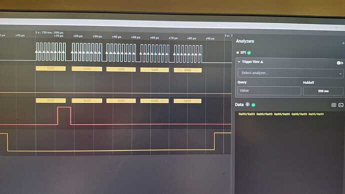
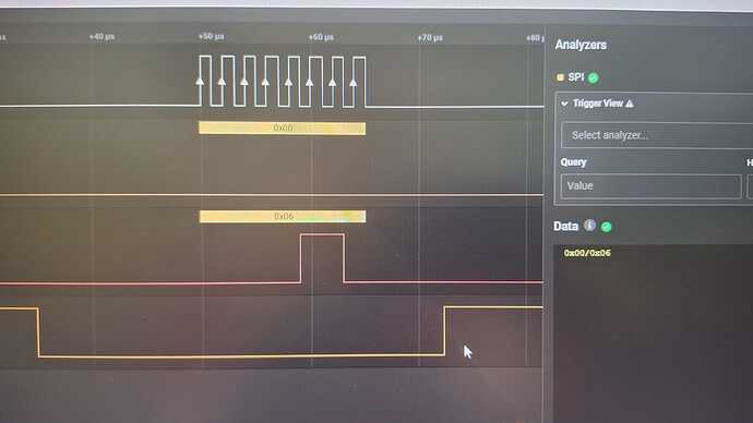
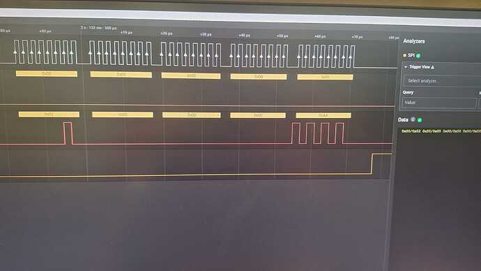
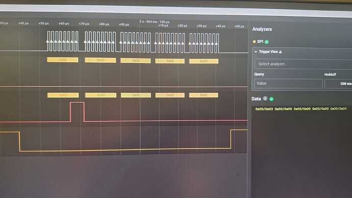
here are some outputs… as you can see I have no response from the FRAM and I got the signals from the FRAM pins directly. This is strange…

Either you have an issue with the hardware or the pin-muxing.

If it were me, if possible I would cut the track and then check on the FRAM to see if it is transmitting.
If it is then it is a pin-muxing issue and something is probably driving the pin low, if not then it is probably the FRAM.

Very cool pictures there Andre!

As @benedict.hewson suggests, can you try and cut the MISO line?
That should then float the pin high if the device-tree pinmux has the pull-up enabled.
Alternatively, you could use a 2K resistor to Vcc, but it shouldn’t be required.

All in all, it looks like you’re very close…

Just one question: You have connected the HĚ…OĚ…LĚ…DĚ… pin to Vcc, yes?

The device tree spec has changed. Consider reviewing am33xx.h to determine what the new device tree bindings are for your custom muxing/node modifications.

For example, your dtsi uses the older IOPAD as apposed to the newer PADCONF, further, the hex addresses, such as 0x95c (in “AM33XX_IOPAD(0x95c, PIN_INPUT | MUX_MODE2)”) are now mapped to constants in the am33xx.h; in the case of “0x95c”, that mapping would be AM335X_PIN_SPI0_CS0.
i.e.
AM33XX_IOPAD(0x95c, PIN_INPUT | MUX_MODE2 might change to something like
AM33XX_PADCONF(AM335X_PIN_SPI0_CS0, PIN_INPUT | MUX_MODE2)

SLR-

looks like there were some hardware problems with the PCB. MISO and MOSI were switched :smile:
Thank you guys for all your help. you all rock :metal:

You can swap MOSI and MISO in the devicetree