Hello everybody,
Newbie here. I’m trying to use a “coin bank” as a case for my BBB. Looks quite promising so far, but in the future I don’t want to open the case to reach the power/reset-switch. I want to make a simple circuit board, enabling me to connect old reset-buttons I slavaged from an old PC (these are connected to cables with connectors, enabling me to bridge the required signals).
I’m quite a newbie (especially on reading hardware manuals), so before I damage anything:
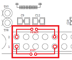
A) Do I read this correctly that a Reset can be archived by bridging Pin10 and GND(either Pin 1 or 2) on P9, respectively bridging Pin 9 and GND for the Powerbutton?
B) Did I locate the pins in the right direction (see attached image)?
Thank you!
Hello everybody,
Newbie here. I'm trying to use a "coin bank" as a case for my BBB. Looks
quite promising so far, but in the future I don't want to open the case
to
reach the power/reset-switch. I want to make a simple circuit board,
enabling me to connect old reset-buttons I slavaged from an old PC (these
are connected to cables with connectors, enabling me to bridge the
required
signals).
I'm quite a newbie (especially on reading hardware manuals), so before I
damage anything:
A) Do I read this correctly that a Reset can be archived by bridging
Pin10
and GND(either Pin 1 or 2) on P9, respectively bridging Pin 9 and GND for
the Powerbutton?
Yes. Be sure you have a kernel and software image that supports
powerdown (or prompting for it) on press of the power button.
B) Did I locate the pins in the right direction (see attached image)?
Yep! 
-Andrew
Another question: The Powerbutton is described at a 5V level. Will I need to put a resitor in my bridge?
As for the working of the button: I’m running a debian-image. After installing the acpi-demon, the power-signal (at least from the onboard-button) works fine.
Thank you!
Another question: The Powerbutton is described at a 5V level. Will I need
to put a resitor in my bridge?
The power button just needs to see the level pulled to ground, there's
an internal pull-up resistor inside the PMIC. To "press" the power
button just pull the power button signal to ground and release it. A
normally open button across the power button signal to ground works
fine.
As for the working of the button: I'm running a debian-image. After
installing the acpi-demon, the power-signal (at least from the
onboard-button) works fine.
Good to hear!
-Andrew
From the plans and schematics I couldn’t find where the power button signal went. I think I finally found it with your help: https://raw.github.com/CircuitCo/BeagleBone-Black/master/BBB_SRM.pdf
Figure 22, labled as PB_IN?
Thank you very much!
PB_IN stands for “Power Button In”
Gerald
So basically the opposite of what I wanted to find(as PWR_BTN should give something out rather than in)? Well I’ll try to search the docs further, until I understand them. Thank you!
Reset is an output. Power button can also be monitored as an output when the power button is pressed. It is a signal. With a pullup. And a switch that shorts that signal to ground. It is intended to connect a button to it to affect the power down function.
But, you can also use it as an output of the action of pressing the button.
Gerald