So, I have noticed in my short time on this Earth that now brushed motors in electronics are being sort of phased out, e.g. power tools and especially with R/C electronics in general.
I decided to try to find a brushed DC motor ESC recently that accepted 3S to 8S LiPo battery packs. No go. This gave me some insight into other research. So, I went down the path…
Brushless motors seem to be where the market is taking us with advanced electronics and powering these devices and controllers like the am62x and other beagleboard.org SBCs may get more complicated as everyone already knows.
new to life? Me too!
Now, I need to find a non-brushed motor controller (ESC) to control something, funny tank style robot, that will accept my commands but is slow (geared). I do not need to fly or control this device at high speeds. That is where my researched ended. It seems people, companies like the personnel at DeWalt, are already manufacturing (starting very recently) brushless drive tools.
Now, no. A power tool does not need to be so smart. At least not to me and driving a geared brushless system seems a bit, more intelligent than using the older electronics from the past.
Do I feel bad for the R & D that goes into manufacturing the new line of tools from various company personnel? No. Times change and I am learning slowly how to adapt a bit more vicarious and easily at times for myself.
side note
They make geared, brushless configurations for smaller electronics if you are willing to do the research and find fitment.
I think the main hassle with brushless is to get the rotating magnetic field, you need something which commutates. Usually they have hall devices built in, which give when to commutate. Still means you need something to read the hall devices, and a bridge to switch the current. This said they work far better. [N.B. Some motors are designed to cog, so they follow the rotating field very strongly, and so you don’t need a feedback loop …]
I see the components are Open Source in that things are well documented. When it says carrier on the printable manual, does this mean supplying a controller for this Motor Controller is needed?
And…are there any plans on what exact board may be needed?
Yes, it’ll be at the typical distributors, probably 1Q27. The media got hold of it early because I brought up pages so TI could link to it when they talk about it at Electronica next week.
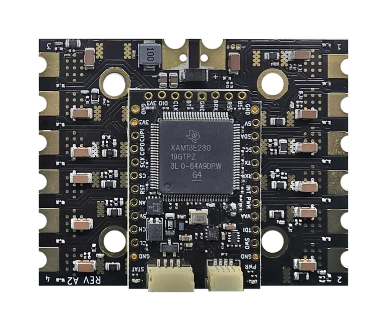
BeagleConnect QuadESC ships with a BeagleConnect Torque soldered down to it. Unless there is some specific requirement, the “mainboard” or “carrier” won’t be sold separately, since pretty much everyone will want a programmed MCU on the QuadESC board. It is just that we will produce BeagleConnect Torque, the processor board or system-on-module board, however you want to call it, separately for those who want a CAN-based microcontroller board that can be connected to different sensors/drivers.
Also, our plan is to ship D-Shot/PWM/DroneCAN enabled firmware pre-programmed on BeagleConnect QuadESC so it is “ready-to-fly”.
It would be great to get requirements here on what folks might want to see as more of a “motion control” firmware, rather than just quadcopter electronic speed control. At 40A continuous, but at only 25V, it isn’t perfect for a lot of robotic arms that have to hold themselves steady, but it is pretty good and probably a LOT more current than a typical racing drone needs. It is a bit of a “tweener”, but I think that’ll make it a lot of fun. With full current/voltage measurement on every channel, not just every motor, I’m expecting people to build things like pick-and-place machines, CNC mills and other robotics like that. The robotic arms with the big holding power are less of a target, in my mind.
You can certainly use Hall sensors, but calling what most electronic speed controllers (ESCs) do “sensorless” has always bugged me—you are sensing, you’re just using the motor phase coils as the sensor. By measuring the phase current and backwards electromotive force (back-EMF) using analog-to-digital converters (ADCs), an observer algorithm can track the rotor’s magnetic angle in real time.
That’s why BeagleConnect QuadESC is designed around field-oriented control (FOC). Using Texas Instruments DRV8323RS three-phase gate drivers with built-in current-sense amplifiers, we get smooth sinusoidal drive down at low speeds without the jerky cogging or stepping you get trying to force open-loop commutation, and without having to run 5-wire Hall harnesses to four different motors.
This makes it a great match for a geared tank or radio-controlled (RC) car, but multirotor flight firmware isn’t going to give you what you want. DShot (a digital throttle protocol common on quadcopters) was designed for spinning propellers in the air, not for low-speed crawling, active braking down a slope, or bidirectional skid-steer control.
We’re planning to run the motion control interface over Controller Area Network (CAN) bus, and pairing it with something like a PocketBeagle 2 with a CAN transceiver is probably the cleanest way to drive the whole rig from Linux.
Before we lock down the QuadESC firmware side, what does your motion control interface actually need to look like over the CAN bus? Are you looking to send velocity targets (revolutions per minute or radians per second), torque and current limits, or something else? And what telemetry do you want reported back? Let’s figure out the interface so it fits what you’re building.
Thank you. I was reading up on the pages that were published early. I cnc machine with BLDC motors sounds horrific in a good sense. Halloween is not out of me yet!
Now, I know. And yes sir, good-ole-chap, the “carrier” is a BeagleConnect Torque. Okay. I am updated…
I was unaware of the “carrier” being something that is in the works and not an already 2020 plus to now SBC from beagleboard.org.
RTF is cool… I am not going to complain.
Oh and Thoughts!
And yes sir about the programmed MCU already being accomplished/done. I cannot complain or would even want to cause a stir about pre-programmed MCU statuses.
It is not easy from what I can tell. .c files galore along with #define calls at a maximum would entail some of what I understand for mcu programming. Anyway, neat and do it! I am sure the builds will be plenty…
Oh and gotcha on the robotic arms being less of a use case. I can always use stepper motors and drivers for building around robotic arms. Time for me to save so when this board approaches release, I can grab one or two…
…or more. It really depends on what is happening to me in my life. I hate rollercoasters and surprises but I can take a punch and release fisty cuffs. Just kiddin’. I cannot wait!
Yes after I posted, I kinda thought cpu fans are brushless, and work. Then obviously have much cogging, try turning one without power on the motor! Yes I’m familiar with joint voltage and current measurements, in a different context. It does take a bit of thought, e.g. you need to know if you are operationally running at a point that is back emf dominated (which is quite typical, you let the motor spin up until back emf balances the drive voltage, then change speed through changing the drive voltage) or you in a domain where voltage drop across the motor imedance dominates (this is unusual, it means most of the electrical power goes as heat in the motor!) Anyway for this to work well, as you have noted you need current measurements as well, this is because of the voltage drop across the motor impedance, that voltage drop is given by the drive current, and you need to include it to do things accurately. Measuring current has its own hardware requirements, you either need to sence voltage across a small resistor in series, or have an inductive coupler. Either way it’s additional hardware - and he’s the main impact is you need an adc to measure. To me it’s very interesting that there is a to chip that does this! I’d not come across it! In space we tend to have discrete solutions. Anyway I’ll browse the TI chip, but like your solution. Edit have now read the data sheet. I like that chip. There are a few assumptions in there think TI has covered most, when sending current it’s usually a very small sense resistor, I say 0.01 Ohm at tops, this is mainly because the resistive part of the motor impedance is typically a few Ohm, with a sense resistor of 1% of that value, the sense resistor will burn up to 1% of the power used, and that will waste power and become hot! Usually I’d aim for just a few mV across the sense resitor. The charge pump for high side switching is interesting, it is just a voltage doubler. This works because the chip has to be driven by the motor drive voltage, that’s interesting means the chip can be driven by ~40V, when most of the internals is probably only 3V. Finally they have an assumption build in, they have the voltage drive as PWM - which makes sense! But the current sense is set up to assume the current only varies slowly (against the PWM frequency). Now this works because all motor impedances have a huge inductive component, and that all the the PWM noise from the drive is smoothed in the current. So the current measurements doesn’t worry about the PWM. My guess is there is an Aplication Note on typical circuits for current sensing designs? TI is usually good with things like that.
My thoughts on this component would be a working CNC set up. Would this actually be possible with this SBC and “carrier”?
Seth
P.S. I noticed that making CNC machines would be possible and I just was trying to get reconfirmation here. I notice some care taken towards preferential treatment of machines that deal with Flying or Mobilizing on grounds. BeagleConnect QuadESC
I just do not see anywhere in the current set of documentation that I have read where it states a CNC capable interface of a set up. Anyway, if you get around to replying, please let me know and if I do not hear from you, no issue. I can always purchase one to start testing.
And read up on the above this morning over breakfast, crux is they take the motor as a LTI (Linear Time Invariant) - and from that fact alone a lot follows. I think it likely that you drive with sinusoidal voltage wave forms, as that what the underlying physics say you have to do to have a rotating magnetic field, and the physics is LTI as well. Now that the system is LTI means with a sinusoidal voltage, the current just also be sinusoidal (this can vary in non linear system - but can’t see much in this system to give any major non linearity). So both current and voltage should be sinusodal, with the same frequency - this means only free parameters are relative phase and amplitude. So what I am wondering is how best to drive. The amplitude and phase can be extracted by downconverting the measurements in quadrature to baseband, an that would give phase and gain type measurements. Only bit I can’t see is now to optimise those for optimal drive. There is some underlying methods, e.g. You pass most energy electrically into the system when phase is zero, and in many systems that is optimal. Optimising gain is tricky, or rather you can just measure it to tell you about the physics of the system. It’s interesting to consider, as going down this line there are only a few things that can be measured from the waveforms - but anyway makes it an interesting system.
Am confused over the design: https://www.beagleboard.org/app/uploads/2026/10/quadesc_mainboard_top_transparent-768x656.webp show the beagle torque dsp mounted on top of the quadesc. But looking at the schematics and the pcb board layout, and the underside shows the bga pads for the raw TI dsp to be mounted on. As a bga, this really needs to be flow soldered in an oven, this is beyond what most amatures can do at home. So what is the plan, to release built up boards? If so when would these be availabe? Is the beagle torque mounted on top, via proper pin connectors? Just trying to work out what the design is! Am half tempted to get a board, just to see how well the theory works with real motors - and see how fast we can get the dsp pwm. My guess is with the power of the ti dsp, may be able to do this at 100kHz, this would then need careful firmware, in particular probably a monotonic kernel with just one interrupt from the pwm, and all processing done in one pwm cycle. This is probable just me thinking in and old school way, of how can we drive the m33 within an inch of its life. This kind of design is old school and takes time, so suspect that you have zepher based solution - I should look into this as to how it works - it would be good to understand.