All, sorry for my slow response - I’ve just seen the comments on the GitHub issue and will mirror my findings there.
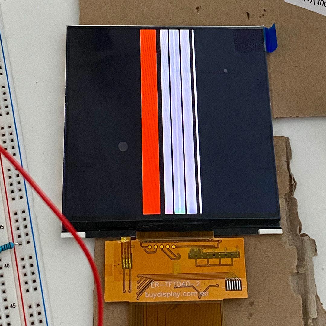
I always get the same effect as described by the OP: every line is looking the same. I’ve got full control over the x-axis, however, and can even run animations.
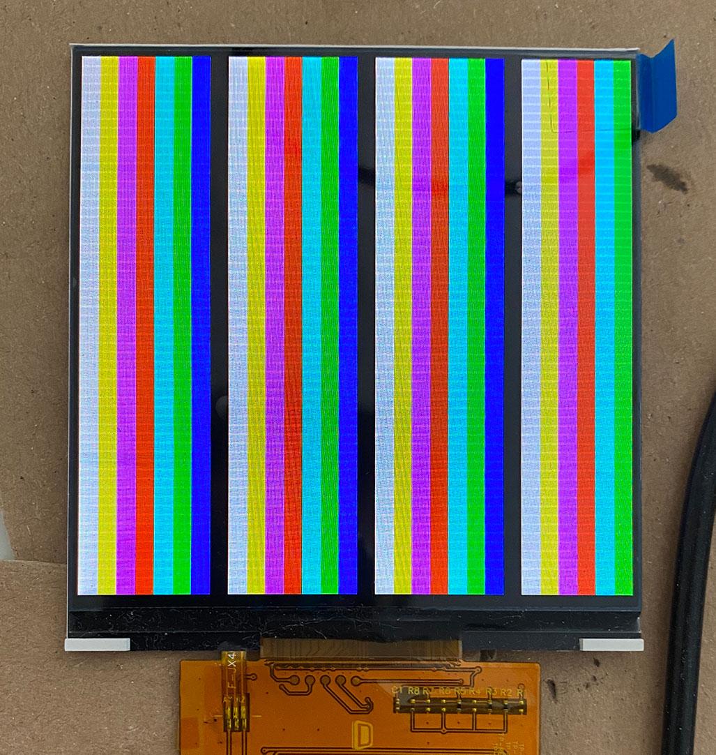
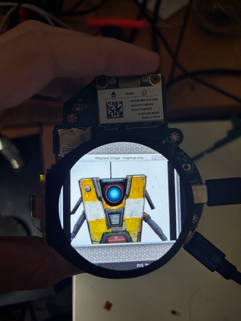
I’m happy to say that I’ve solved it. Or, rather, that I had a solution provided to me. What you’re describing (and your images) seem extremely similar to some of the failure modes I was observing, and I likewise found next to nothing online about this. Plenty for the ST7701, which is apparently just different enough.
The short answer is one that should frustrate you, especially if you were using the same Sitronix data sheet that I was: NOT ALL OF THE COMMANDS ARE LISTED IN THE DATASHEET
I ended up emailing my contact at Shanghai TDO, and she shared with me the init sequence that their engineers use:
#if 1 //zheng shao
SPI_WriteComm(0xFF);
SPI_WriteData(0x77);
SPI_WriteData(0x01);
SPI_WriteData(0x00);
SPI_WriteData(0x00);
SPI_WriteData(0x10);
SPI_WriteComm(0xC0);
SPI_WriteData(0x3B);
SPI_WriteData(0x00);
SPI_WriteComm(0xC1);
SPI_WriteData(0x0B); //VBP
SPI_WriteData(0x02);
SPI_WriteComm(0xC2);
SPI_WriteData(0x00);
SPI_WriteData(0x02);
SPI_WriteComm(0xCC);
SPI_WriteData(0x10);
SPI_WriteComm(0xCD);
SPI_WriteData(0x08);
SPI_WriteComm ( 0xB0); //Positive Voltage Gamma Control
SPI_WriteData ( 0x02);
SPI_WriteData ( 0x13);
SPI_WriteData ( 0x1B);
SPI_WriteData ( 0x0D);
SPI_WriteData ( 0x10);
SPI_WriteData ( 0x05);
SPI_WriteData ( 0x08);
SPI_WriteData ( 0x07);
SPI_WriteData ( 0x07);
SPI_WriteData ( 0x24);
SPI_WriteData ( 0x04);
SPI_WriteData ( 0x11);
SPI_WriteData ( 0x0E);
SPI_WriteData ( 0x2C);
SPI_WriteData ( 0x33);
SPI_WriteData ( 0x1D);
SPI_WriteComm ( 0xB1); //Negative Voltage Gamma Control
SPI_WriteData ( 0x05);
SPI_WriteData ( 0x13);
SPI_WriteData ( 0x1B);
SPI_WriteData ( 0x0D);
SPI_WriteData ( 0x11);
SPI_WriteData ( 0x05);
SPI_WriteData ( 0x08);
SPI_WriteData ( 0x07);
SPI_WriteData ( 0x07);
SPI_WriteData ( 0x24);
SPI_WriteData ( 0x04);
SPI_WriteData ( 0x11);
SPI_WriteData ( 0x0E);
SPI_WriteData ( 0x2C);
SPI_WriteData ( 0x33);
SPI_WriteData ( 0x1D);
SPI_WriteComm(0xFF);
SPI_WriteData(0x77);
SPI_WriteData(0x01);
SPI_WriteData(0x00);
SPI_WriteData(0x00);
SPI_WriteData(0x11);
SPI_WriteComm(0xB0);
SPI_WriteData(0x5d);//5d
SPI_WriteComm(0xB1); //VCOM amplitude setting
SPI_WriteData(0x43); //43
SPI_WriteComm(0xB2); //VGH Voltage setting
SPI_WriteData(0x81); //12V
SPI_WriteComm(0xB3);
SPI_WriteData(0x80);
SPI_WriteComm(0xB5); //VGL Voltage setting
SPI_WriteData(0x43); //-8.3V
SPI_WriteComm(0xB7);
SPI_WriteData(0x85);
SPI_WriteComm(0xB8);
SPI_WriteData(0x20);
SPI_WriteComm(0xC1);
SPI_WriteData(0x78);
SPI_WriteComm(0xC2);
SPI_WriteData(0x78);
SPI_WriteComm(0xD0);
SPI_WriteData(0x88);
SPI_WriteComm(0xE0);
SPI_WriteData(0x00);
SPI_WriteData(0x00);
SPI_WriteData(0x02);
SPI_WriteComm(0xE1);
SPI_WriteData(0x03);
SPI_WriteData(0xA0);
SPI_WriteData(0x00);
SPI_WriteData(0x00);
SPI_WriteData(0x04);
SPI_WriteData(0xA0);
SPI_WriteData(0x00);
SPI_WriteData(0x00);
SPI_WriteData(0x00);
SPI_WriteData(0x20);
SPI_WriteData(0x20);
SPI_WriteComm(0xE2);
SPI_WriteData(0x00);
SPI_WriteData(0x00);
SPI_WriteData(0x00);
SPI_WriteData(0x00);
SPI_WriteData(0x00);
SPI_WriteData(0x00);
SPI_WriteData(0x00);
SPI_WriteData(0x00);
SPI_WriteData(0x00);
SPI_WriteData(0x00);
SPI_WriteData(0x00);
SPI_WriteData(0x00);
SPI_WriteData(0x00);
SPI_WriteComm(0xE3);
SPI_WriteData(0x00);
SPI_WriteData(0x00);
SPI_WriteData(0x11);
SPI_WriteData(0x00);
SPI_WriteComm(0xE4);
SPI_WriteData(0x22);
SPI_WriteData(0x00);
SPI_WriteComm(0xE5);
SPI_WriteData(0x05);
SPI_WriteData(0xEC);
SPI_WriteData(0xA0);
SPI_WriteData(0xA0);
SPI_WriteData(0x07);
SPI_WriteData(0xEE);
SPI_WriteData(0xA0);
SPI_WriteData(0xA0);
SPI_WriteData(0x00);
SPI_WriteData(0x00);
SPI_WriteData(0x00);
SPI_WriteData(0x00);
SPI_WriteData(0x00);
SPI_WriteData(0x00);
SPI_WriteData(0x00);
SPI_WriteData(0x00);
SPI_WriteComm(0xE6);
SPI_WriteData(0x00);
SPI_WriteData(0x00);
SPI_WriteData(0x11);
SPI_WriteData(0x00);
SPI_WriteComm(0xE7);
SPI_WriteData(0x22);
SPI_WriteData(0x00);
SPI_WriteComm(0xE8);
SPI_WriteData(0x06);
SPI_WriteData(0xED);
SPI_WriteData(0xA0);
SPI_WriteData(0xA0);
SPI_WriteData(0x08);
SPI_WriteData(0xEF);
SPI_WriteData(0xA0);
SPI_WriteData(0xA0);
SPI_WriteData(0x00);
SPI_WriteData(0x00);
SPI_WriteData(0x00);
SPI_WriteData(0x00);
SPI_WriteData(0x00);
SPI_WriteData(0x00);
SPI_WriteData(0x00);
SPI_WriteData(0x00);
SPI_WriteComm(0xEB);
SPI_WriteData(0x00);
SPI_WriteData(0x00);
SPI_WriteData(0x40);
SPI_WriteData(0x40);
SPI_WriteData(0x00);
SPI_WriteData(0x00);
SPI_WriteData(0x00);
SPI_WriteComm(0xED);
SPI_WriteData(0xFF);
SPI_WriteData(0xFF);
SPI_WriteData(0xFF);
SPI_WriteData(0xBA);
SPI_WriteData(0x0A);
SPI_WriteData(0xBF);
SPI_WriteData(0x45);
SPI_WriteData(0xFF);
SPI_WriteData(0xFF);
SPI_WriteData(0x54);
SPI_WriteData(0xFB);
SPI_WriteData(0xA0);
SPI_WriteData(0xAB);
SPI_WriteData(0xFF);
SPI_WriteData(0xFF);
SPI_WriteData(0xFF);
SPI_WriteComm(0xEF);
SPI_WriteData(0x10);
SPI_WriteData(0x0D);
SPI_WriteData(0x04);
SPI_WriteData(0x08);
SPI_WriteData(0x3F);
SPI_WriteData(0x1F);
SPI_WriteComm(0xFF);
SPI_WriteData(0x77);
SPI_WriteData(0x01);
SPI_WriteData(0x00);
SPI_WriteData(0x00);
SPI_WriteData(0x13);
SPI_WriteComm(0xEF);
SPI_WriteData(0x08);
SPI_WriteComm(0xFF);
SPI_WriteData(0x77);
SPI_WriteData(0x01);
SPI_WriteData(0x00);
SPI_WriteData(0x00);
SPI_WriteData(0x00);
#if 0
WriteComm (0xFF);
WriteData (0x77);
WriteData (0x01);
WriteData (0x00);
WriteData (0x00);
WriteData (0x12);
WriteComm (0xD1);
WriteData (0x81);
WriteData (0x08);
WriteData (0x03);
WriteData (0x20);
WriteData (0x08);
WriteData (0x01);
WriteData (0xA0);
WriteData (0x01);
WriteData (0xE0);
WriteData (0xA0);
WriteData (0x01);
WriteData (0xE0);
WriteData (0x03);
WriteData (0x20);
WriteComm (0xD2);
WriteData (0x08);
#endif
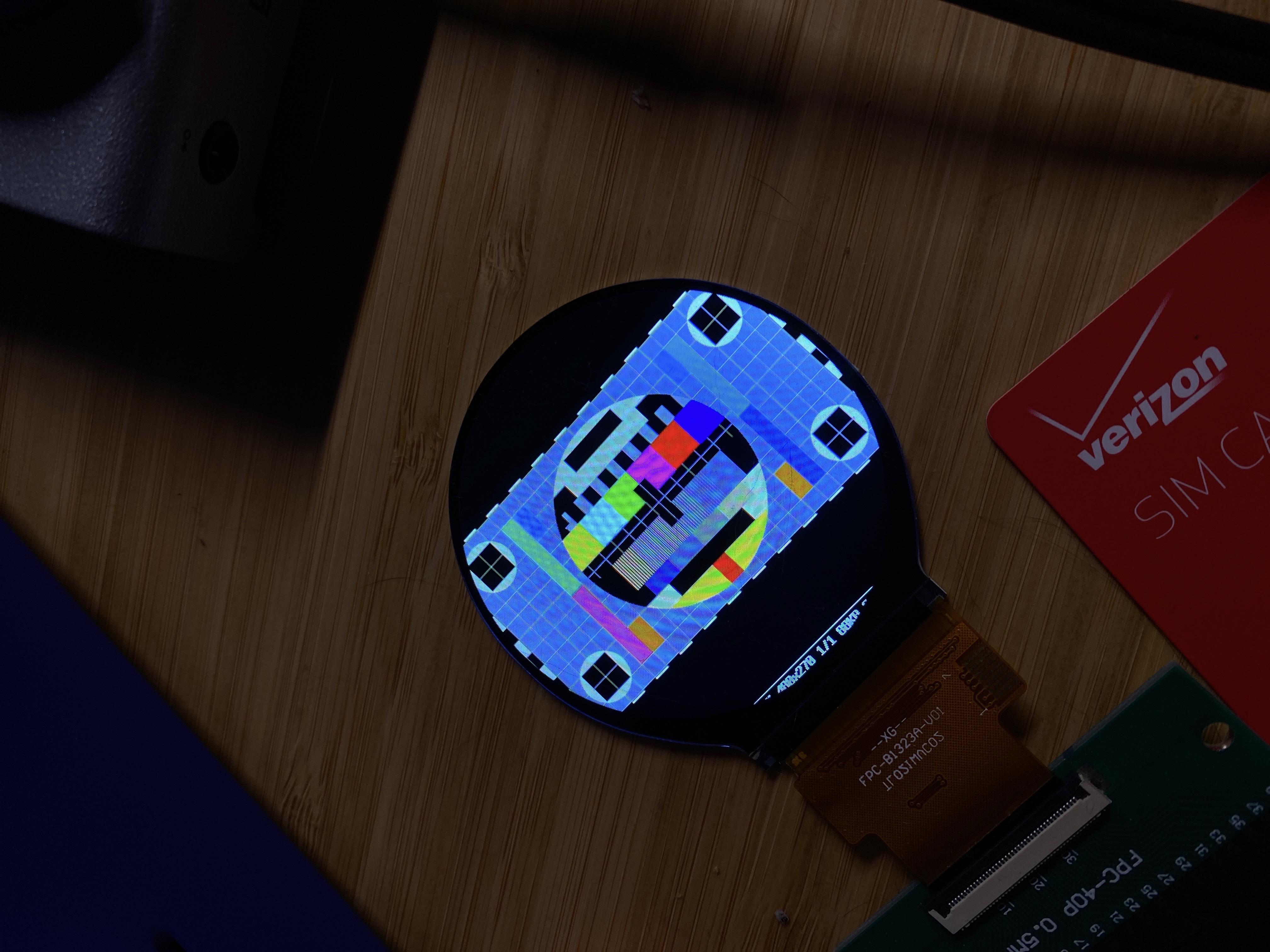
/////////////////Bring up the internal test picture///////////////////////////////////
SPI_WriteComm(0x11);
Delay(120);
SPI_WriteComm(0x29);
SPI_WriteComm(0x36);
SPI_WriteData(0x00);
SPI_WriteComm(0x3A);
SPI_WriteData(0x60);//0x60 18bit 0x50 16bit
#endif
You can see my version of it here: ST7701S-SPI-Driver/src/sequence_tdo.rs at master · ironblock/ST7701S-SPI-Driver · GitHub
I translated the commands that I was able to look up, but there’s a HUGE block of them that are nowhere in the docs, so I just sent them blind: ST7701S-SPI-Driver/src/sequence_tdo.rs at master · ironblock/ST7701S-SPI-Driver · GitHub
So ultimately, I have no idea what’s in those commands that could be so critical to a ST7701S display working that it wouldn’t be in the datasheet for the chip, but evidently the “unscramble display and make it actually work” command is somewhere in there.
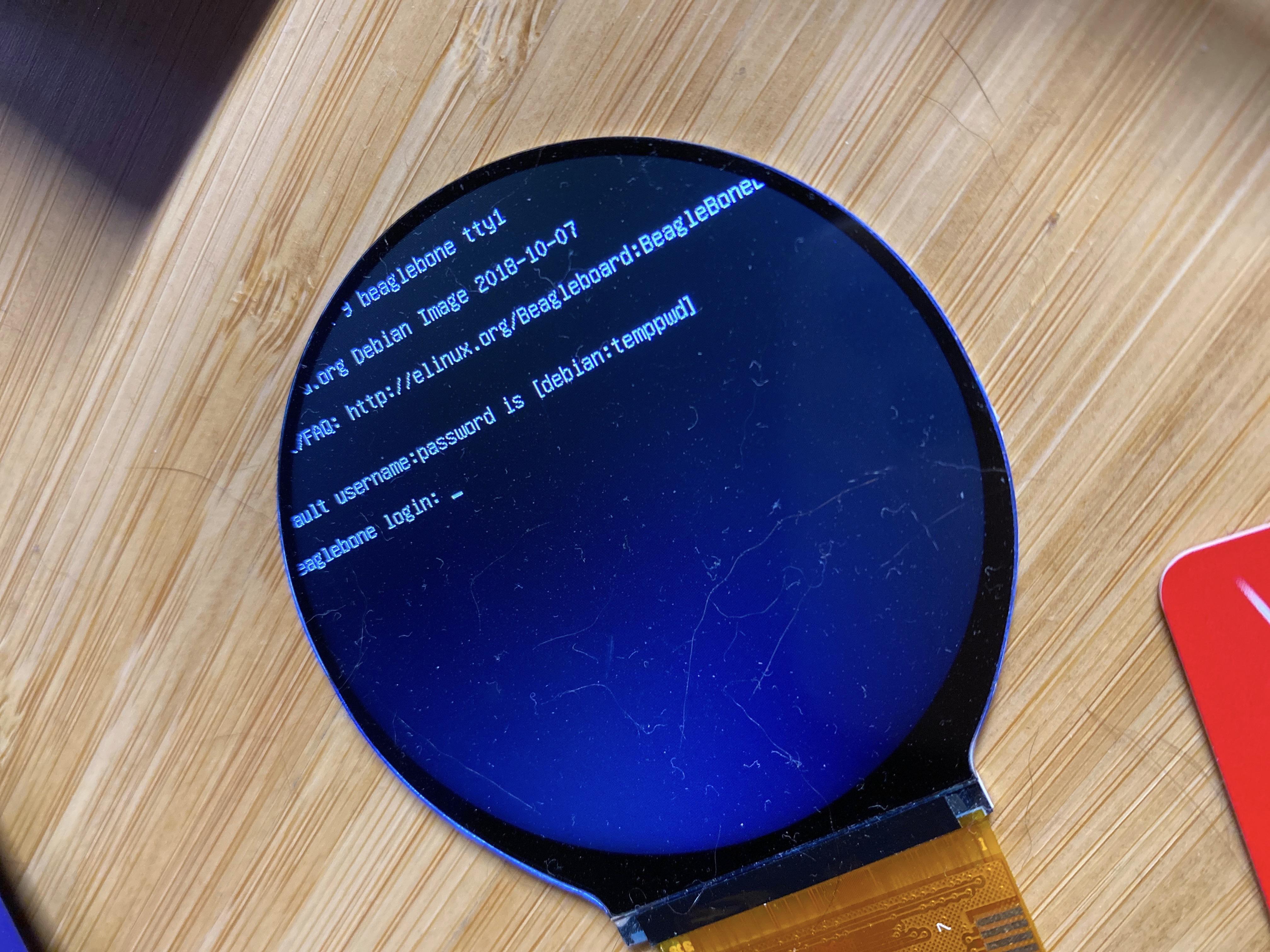
Please let me know if you try this, and let me know if it works for you.