Gas Sensors and Testing for PPM of CO2

Hello,

I am currently researching ideas involving ppm of CO2 in a small dwelling. I think the square footage is 1728. Now, with the basics of a small dwelling and eight foot ceilings, 1728 * 8 gives a reasonable volume of living quarters to deduce the ppm of CO2 in the home.

So, from what little research I have completed so far, I have noticed that ppm can be configured like so:

ppm = grams of solute / grams of solution * 1000000
  1. So, in my case here with measurements intact
    a. Grams of Solute is molecular weight of CO2 which is about 44.009.
    b. Grams of solution from what I think it is currently is the volume of the interior of the measured space or 13824.
    c. 1000000 is the part of the solution I do not fully understand.

Either way, more research will take place…

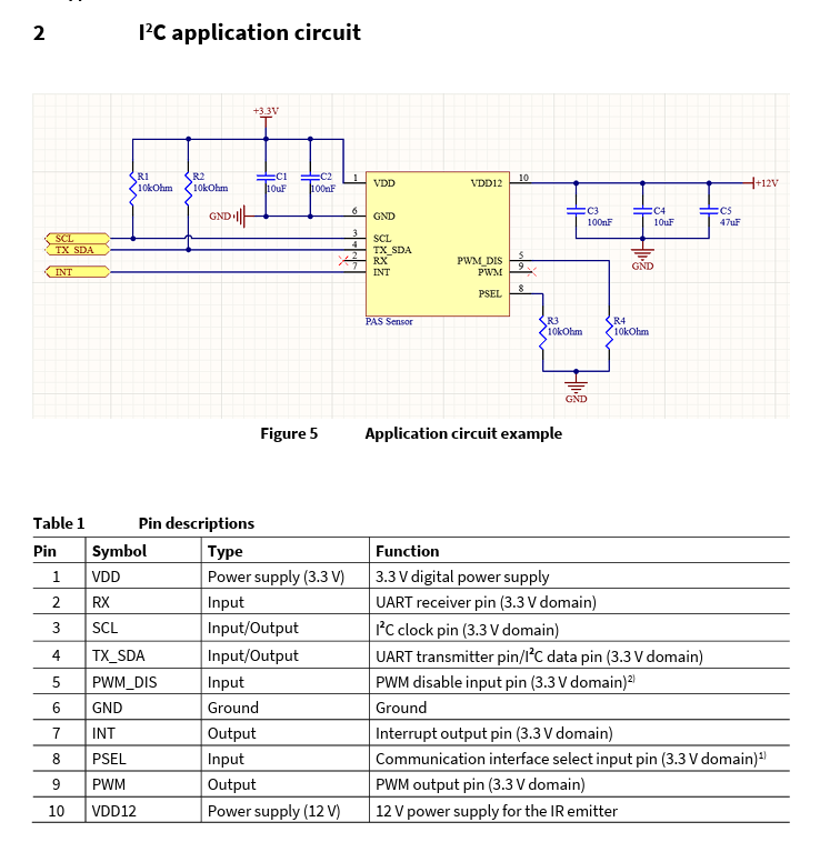
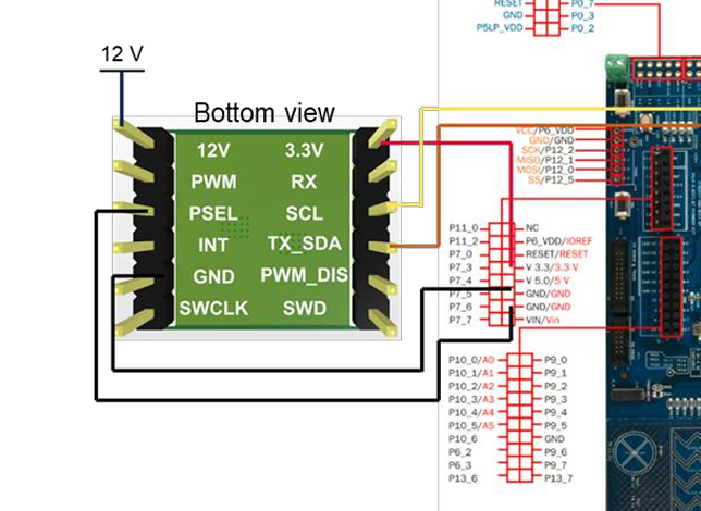
So, if I was to use a BeagleBone Black with the 32-bit processor to measure via i2c and a module for gas sensing, could this be a simple program or is it more in depth than you all know I can handle?

I found a good article on the docs.beagleboard.org pages under The BeagleBone Cookbook for i2c and smbus.

So far, this is all I have currently:

#!/usr/bin/python3
 
# from docs.beagleboard.org and the BeagleBone-Cookbook 
 
import time
import smbus
 
ms = 1000
bus = smbus.SMBus(1)
addr = 0x28
 
while True:
    data = bus.read_byte_data(addr, 0)
    print("Gas per ______ " + str(data))
    time.sleep(ms/1000)

The output is 80. Now, when I change the addr of the hexadecimal value, I get 128.

This is what I was going to do…

#!/usr/bin/python3
 
# from docs.beagleboard.org and the BeagleBone-Cookbook 
 
import time
import smbus
 
ms = 1000
bus = smbus.SMBus(1)
addr = 0x28 # Could be 0x50
 
while True:
    ppm = 44.009 / 13824 * 1000000
    print("The ppm of CO2 is...: " + int(ppm))

    data = bus.read_byte_data(addr, 1)
    print(" " + str(data))
    time.sleep(ms/1000)

Does anyone see issues or nonacceptable referencing?

Seth

P.S. I guess I am missing where to place the address alongside my PPM valuing.

The source will need work. Okay.

I have been reading more and porting the hardware for the source slowly.

If anyone is working on it, here is the link to the module: XENSIV™ PAS CO2 Mini Evaluation Board - Infineon Technologies .

It directly can be an output of ppm without having to decipher any math for some reason…hmm.

Seth

P.S. I read over the connections and picked up on source work slowly. Now, time to learn that darn datasheet!

Update

The datasheet shows a test accuracy gets a better reading when 90 seconds have passed before/after each read. So, I should hold off on reading continuously like before now…blah.

So,

I was thinking I could directly connect, if people are following along with the Xensiv PAS CO2 detection board, i2c without any other circuitry. Nope. I need additional circuitry because of not having the main board with all the fancy-schmancy circuits done and configured. Sheesh…

So, that is it. That will be the circuit to make for the build…

I am still working on the ins and outs of the process, programming, and less guessing.

Seth

P.S. So, it has only i2c (two pin of course), 3.3v logic, 12v power for an IR Emitter, and if I choose to have an interrupt, I can activate that too.

This is more fun! The motors are sort of on hold for now because of some faulty drivers I purchased a while back. Anyway…on with the fun!

Screenshot 2024-01-16 174826

As you can tell, this is a 3.3v logic supply to the part but…

  1. 12v is needed to power part of the IR Emitter.
  2. Can I use 12v without GND?
  3. The “schematic” from above shows 12v to one pin and no GND.
  4. I also see it is a particular supply symbol which I have not identified yet…

Does anyone know what type of symbol the 12v pin is currently?

Seth

Update

From what I can tell, it is a DC power source with no GND. Does anyone have any ideas on this schematic?

  1. I will try the application circuit in one of the photos from above.
  2. I will return service with the circuit applied.

Okay,

For you programmers out here in BeagleBoard.org land…

  1. Does this source work? Why does it work for a bit and then alternate to error?
#!/usr/bin/python3

import os
import sys
from time import sleep
import smbus

bus = smbus.SMBus(1)
addr = 0x28

SENS_STS = 0x01
PRES_REF_H = 0x0B
PRES_REF_L = 0x0C
MEAS_RATE_H = 0x02
MEAS_RATE_L = 0x03
MEAS_CFG = 0x04

MEAS_STS = 0x07

CO2PPM_H = 0x05
CO2PPM_L = 0x06

OnePlus1 = 0
OnePlus2 = 0

try:
    rack = int(input("Please type a 1 or 0, thank you... "))
    while True:
        if rack >= 0:
            bus.read_byte_data(addr, SENS_STS)
            bus.read_byte_data(addr, PRES_REF_H)
            bus.read_byte_data(addr, PRES_REF_L)
            bus.read_byte_data(addr, MEAS_RATE_H)
            bus.read_byte_data(addr, MEAS_RATE_L)
            bus.read_byte_data(addr, MEAS_CFG)
            bus.read_byte_data(addr, MEAS_STS)
            OnePlus1 = bus.read_byte_data(addr, CO2PPM_H) << 8
            sleep(5)
            OnePlus2 = bus.read_byte_data(addr, CO2PPM_L) >> 8
            sleep(5)
            bus.write_byte_data(addr, SENS_STS, 0x00)
            bus.write_byte_data(addr, MEAS_RATE_H, 0x00)
            bus.write_byte_data(addr, MEAS_RATE_L, 0x0A)
            bus.write_byte_data(addr, MEAS_CFG, 0x02)
            sleep(0.5)
            result = int(OnePlus1 + OnePlus2)
            print("The result of this PPM in the CO2 around here is: {}".format(result))
        else:
            bus.write_byte_data(addr, PRES_REF_H, 0x03)
            bus.write_byte_data(addr, PRES_REF_L, 0xF5)
            bus.write_byte_data(addr, MEAS_RATE_H, 0x00)
            bus.write_byte_data(addr, MEAS_RATE_L, 0x0A)
            bus.write_byte_data(addr, MEAS_CFG, 0x01)
            result = (OnePlus1 + OnePlus2)
            print("PPM of CO2 in your home is: {}".format(result))
            sleep(1)

except KeyboardInterrupt:
    print("Done for now!")
    pass

I am currently trying to use smbus for discussing to/from the chip on the module. The circuit is complete and it works…no issue with the circuit any longer.

…

I am looking for anyone to give feedback on my terrible programming abilities so far. I am still practicing i2c source and need input. Please send a misnomer.

Ha.

Seth

P.S. Is that looks mildly okay, okay. If it needs work, please let me know exactly where I will need to alter what in the source!

  1. Can I use 12v without GND?
    no, the 12V supply gnd will need to connected to GND pin.
    think about your 12V car battery, if only the 12V side is connected to the battery, the car will not start. :slight_smile:
1 Like

the else part will never be executed unless a negative number is entered. “>=” will cover both 0 and 1 input and all other inputs higher than 0

looking through the data sheet,
After each power-on reset, bit SENS_STS.SEN_RDY is set to confirm that the sensor
has initialized correctly.
your not checking this, for reliable readings after POR you might want to.

1 Like

I will check into the SENS_STS.SEN_RDY confirmation. Thank you.

Seth

P.S. I have the programming manual so far. I will need to get to know the datasheet a bit better obviously. Blah. Thank you again…until next time!

@amf99 ,

So, this is odd.

The website with the datasheet will not allow me to view the i2c data for the device any longer.

I tried to save the datasheet and review it once more. Luckily, I have one stashed somewhere around here and I will most likely use UART now instead of i2c for purposes.

Anyway, right. I am applying int instead of a more, well-rounded input.

if rack >= 0:
    int("Blah", blah)

@amf99 , and guess what and I really want to admit for some reason…

1. Cap One negative touched Cap Two positive...

and guess what took place?

2. I will tell now! The positive of Cap One disappeared while the negative held on.

I probably need to do something else with the input and output to make it more well-rounded for this purpose.

Seth

P.S. The code so far is just a quick run through without it being thorough and to the point. So, thank you for your words so far. I like to discuss source still (sort of). I am usually too reluctant and uneducated in the source dept. This creates short sightedness on my part with a lot of following stress to make up for what I lack (research and knowledge).

I am still working on this device. I will update this post so people may be able to post it on the portion of the WWW for openbeagle.org or another site.

The speaking to the chip via smbus has proved valuable. I am reading CO2 levels and progressing with the source a bit while chatting to the chip and outputting instances of comprehension.

Seth

P.S. The above code is not great or even good while using bytes. Some people online think I should use words instead of bytes. I am not so sure since I am sort of new to gas sensing with CO2. Anyway, the sensor works, i.e. phew.

If someone would want to use this device and write up, let me know. I will make it available for use, copying, and along with beagleboard.org licensing requirements.

Hello,

Outside of not checking for the SEN_RDY, I have written some new source… I am not expecting you to review everything from the datasheet to help out. It is not that big of a deal but…

  1. If you see rookie programming mistakes in my source, please point them out!

Seth

#!/usr/bin/python3

import os
import sys
from time import sleep
import smbus
import struct

bus = smbus.SMBus(1)
addr = 0x28

SENS_STS = 0x01
PRES_REF_H = 0x0B
PRES_REF_L = 0x0C
MEAS_RATE_H = 0x02
MEAS_RATE_L = 0x03
MEAS_CFG = 0x04

MEAS_STS = 0x07

CO2PPM_H = 0x05
CO2PPM_L = 0x06

OnePlus1 = 0x00
OnePlus2 = 0x00

bus.read_byte_data(addr, SENS_STS)
bus.read_byte_data(addr, PRES_REF_H)
bus.read_byte_data(addr, PRES_REF_L)
bus.read_byte_data(addr, MEAS_RATE_H)
bus.read_byte_data(addr, MEAS_RATE_L)
bus.read_byte_data(addr, MEAS_CFG)
bus.read_byte_data(addr, MEAS_STS)
OnePlus1 = bus.read_byte_data(addr, CO2PPM_H) << 8
sleep(5)
OnePlus1 |= bus.read_byte_data(addr, CO2PPM_L)
sleep(5)

try:
    alt = int(input("Please type an int...: "))
    while True:
        if alt == 0 and alt <= 100:
            bus.write_byte_data(addr, SENS_STS, 0x00)
            bus.write_byte_data(addr, MEAS_RATE_H, 0x00)

            bus.write_byte_data(addr, MEAS_RATE_L, 0x0A)
            bus.write_byte_data(addr, MEAS_CFG, 0x02)
            sleep(0.5)
            bus.write_byte_data(addr, CO2PPM_L) << 8
            result1 = hex(OnePlus1)
            print("The result of this PPM in the CO2 around here is: {}".format(result1))

        # Help from Stack Exchange but it does nothing correctly?
        elif alt >= 101:
            hex_data = "0x28"
            bytes_data = bytes.fromhex(hex_data)
            num_ints = len(bytes_data) // 2
            fmt = '>' + 'h' * num_ints
            result = struct.unpack(fmt, bytes_data)
            print(result)

        else:
            pass
#            arm = binascii.unhexlify(result1, 16)
#            bar = binascii.unhexlify(result2, 16)
#            print("Um...: {}".format(arm))
#            print("Yep...: {}".format(bar))

except (KeyboardInterrupt, ValueError):
    print("Done for now and you did not answer with a hexadecimal value...")
    pass

To anyone else wanting to comment, please add options and/or ideas at will!

Seth

ya only need “alt <= 100” this covers “alt == 0”

the bytes.fromhex() is only expecting the hex value, not sure the “0x” is needed on hex_data

“<< 8” ??, maybe a copy paste issue

About the C & P issue. It does not work.

I tried that and 16 as so: bus.write_byte_data(addr, CO2PPM_L) << 8 and << 16.

I will try without the 0x frontend like so: hex_data = "28".

I am new to smbus, i2c, and programming this chip on the CO2 sensor and from the BBB i2c peripheral.

I really never messed with i2c before this time (sort of). So, I will keep trying. I received some output back with my print statement:

First, the lines of output that appeared were: 256, 254, 256. 

This was from the print statement(s).

Then, I changed the bus.read_byte_data(addr, N) lines to be before the while loop and if/elif statements.

I think the lines for OnePlus1 = , like you think, are a bit incorrect.

And then, I tried in the if statement, bus.write_byte_data(addr, CO2PPM_L) << 8.

I started then to receive very high numerical values. Somewhere in the 16000’s.

Seth

P.S. I will keep with it and I will read the link suggested. If you have any words of wisdom surrounding the i2c-smbus protocol(s), please let me know. There is a programmer’s guide for this idea but it is for Arduino which I think is not related to Linux, the BBB, and armhf type machines. I tried to translate but came up short on porting the i2c lib. for Arduino to Linux Debian. Okay…bbl. Work and other duties call. Thank you for helping so far.

your doing a write not read,
as for smbus i2c, as far as i can figure, it only does 8 bit data, no 16 bit register reads/writes

your writing, not reading, the “<< 8” is valid for a read.

so you don’t do C-coding ??

1 Like

As you can tell, I do not do anything well. I can attempt it so far.

Seth

P.S. Oh and about that C/C++ language, I pick up on things here and there but I do not know the language from A to Z.

Update on programming

In a try except clause, I found this idea to be useful!

except OverflowError as err:
    print(err)

Neat!

I am working on more articulate programming and I came across an older book. Anyway, here is some code.

import math
INPUTS = [
(1000, 900, 0.1),
(100, 90, 0.1),
(10, 9, 0.1),
(1, 0.9, 0.1),
(0.1, 0.09, 0.1),
]
print('{:^8} {:^8} {:^8} {:^8} {:^8} {:^8}'.format(
'a', 'b', 'rel_tol', 'abs(a-b)', 'tolerance', 'close')
)
print('{:-^8} {:-^8} {:-^8} {:-^8} {:-^8} {:-^8}'.format(
'-', '-', '-', '-', '-', '-'),
)
fmt = '{:8.2f} {:8.2f} {:8.2f} {:8.2f} {:8.2f} {!s:>8}'
for a, b, rel_tol in INPUTS:
close = math.isclose(a, b, rel_tol=rel_tol)
tolerance = rel_tol * max(abs(a), abs(b))
abs_diff = abs(a - b)
print(fmt.format(a, b, rel_tol, abs_diff, tolerance, close))

It is beautifully formatted and it is awkwardly factual. The comparison creates one false close while the rest are true because of how the 0.1 and 0.09 are compared with the error.

The isclose() gets passed a rel_tol which in this instance and I quote, To use a fixed or “absolute” tolerance, pass abs_tol instead of rel_tol, which is comparative.

It gets better! The book, “The Python3 Standard Library by Example (Hellmann, 2017),” is a bit dated because of advancements in ideas, relational data, and concepts in general but is a winner.

The book is full of informative ideas and good, stern addressing to Python3. Anyway, if you use that snippet or change it to your liking, please MLA format the thing better than I have done here.

should I use quotation marks in the read?

Seth

P.S. Is that, SENS_STS.SEN_RDY, the SEN_RDY for SENS_STS needs to be stated to see if that transaction is allowed and can be acted on/allocated?

no on the quotation marks,

1 Like

@amf99

You asked previously about C/C++ experience. I found a short script that may be able to be used. See below:

#include <stdio.h>
#include <stdlibi.h>
#include <fcntl.h>
#include <unistd.h>
#include <linux/i2c-dev.h>
#include <sys/ioctl.h>

int main(int argc, char *argv[]) {
    int file;
	char *filename = "/dev/bone/i2c/1";
	int addr = 0x28;
	
	// Open the i2c BUS
	if ((file = open(filename, O_RDWR)) < 0) {
	    perror("Failed to open...");
		exit(1);
    }
	
	// Use the Slave Address via ioctl calls
	if (ioctl(file, I2C_SLAVE, addr) < 0) {
	    perror("Failure...the bus cannot access or chat with the slave");
		close(file);
		exit(1);
	}
	
	char buf[10] = {0};
	buf[0] = 0x00 // command register address
	buf[1] = 0x00 // write this data
	
	// Write to the i2c device
	if (write(file, buf, 2) != 2) {
	    perror("Failed to write to the i2c device");
	} else {
	    printf("The data write was a success!\n");
	}
	
	// Read from the device after the writing to the device
	if (read(file, buf, 2) != 2) {
	    perror("This is a failed read...");
	} else {
	    printf("Data read: %02x %02x\n", buf[0], buf[1]);
	}
	
	close(file);
	return 0;
}

So, something along these lines may be able to be used…

I will attempt changes and port other ideas to it.

Seth

P.S. I guess I will need a .h file for the other hexadecimal addresses that need to be used…

Any guidance on this idea will be helpful. Also, if you want to see the Arduino code they have listed, this may help you help me?