Hello guys,
Someone please could help/explain me how isthe best and security way to connect 5v relays on BBB ?
I 'm planning usage this relay http://www.dx.com/en/p/arduino-5v-relay-module-blue-black-121354 or this relay board http://www.dx.com/en/p/8-channel-5v-relay-module-board-for-arduino-red-156424
Thank you
Best regards,
Carlos
Use an NPN transistor. (2N3904, 2N2222, etc)
Connect the emitter to ground.
Connect the collector to one side of the coil. Connect +5V to the other side of the coil.
Connect a 10K resistor between the I/O pin and the base of the transistor.
That’s it J
“No one could make a greater mistake than he who did nothing because he could do only a little.”
“All that is necessary for the triumph of evil is that good men do nothing” Edmond Burke (1729 - 1797)
http://www.packtpub.com/building-a-home-security-system-with-beaglebone/book
You should also put a diode across the relay (reversed polarity, so the
Hello guys, have you any draw about these circuit mean, I 'm not so good with this
In case of use the 8 relays board, need I do one circuit to each relay ?
Thank you,
Carlos
jan
December 25, 2014, 11:04am
5
The boards your links point to seem to have integrated drivers.
/Janne
----Ursprungligt meddelande----
The circuit it will be like this ? Replacing the RB and RL by 10K resitor…?
Thanks a lot and Merry Christmas for everyone!!
Carlos
Hey Carlos;
Excellent attempt !
RB is 10K and RL is the relay coil. (They probably used ‘L’ to mean coil).
Also, if the transistor has too much gain, and the relay doesn’t turn off completely.
Just connect a 100K resistor between the base of the transistor (B) and 0V on your schematic.
…. And a Merry Christmas to you too J
Bill
“No one could make a greater mistake than he who did nothing because he could do only a little.”
“All that is necessary for the triumph of evil is that good men do nothing” Edmond Burke (1729 - 1797)
http://www.packtpub.com/building-a-home-security-system-with-beaglebone/book
WulfMan
December 25, 2014, 4:05pm
8
You people drive me crazy sometimes
use one of these
ULN2803http://www.ti.com/lit/ds/symlink/uln2803a.pdf
DTJF
December 25, 2014, 4:28pm
9
Hi Carlos, and marry Christmas to everyone.
At least we helped ASSHOLE !
That’s more than you did, until we stepped and a least tried !
“No one could make a greater mistake than he who did nothing because he could do only a little.”
“All that is necessary for the triumph of evil is that good men do nothing” Edmond Burke (1729 - 1797)
http://www.packtpub.com/building-a-home-security-system-with-beaglebone/book
WulfMan
December 25, 2014, 5:55pm
11
Merry christmas to you too.
Woah big guy. No need to get all wound up over nothing. You guys drive me crazy too, but I do not know electronics as well as most here.
Perhaps you should go write a book Zen Buddhism or something- Then perhaps you’ll figure out that the whole world is not “out to get you”.
Merry Christmas
Hello Guys,
Thank you for all for ideas/suggestions.
Thanks
Carlos
Hello Guys,
Thank you so much by ideas/suggestions.
I 'll test it!!!
Thanks again!!
Carlos
Hello Guys,
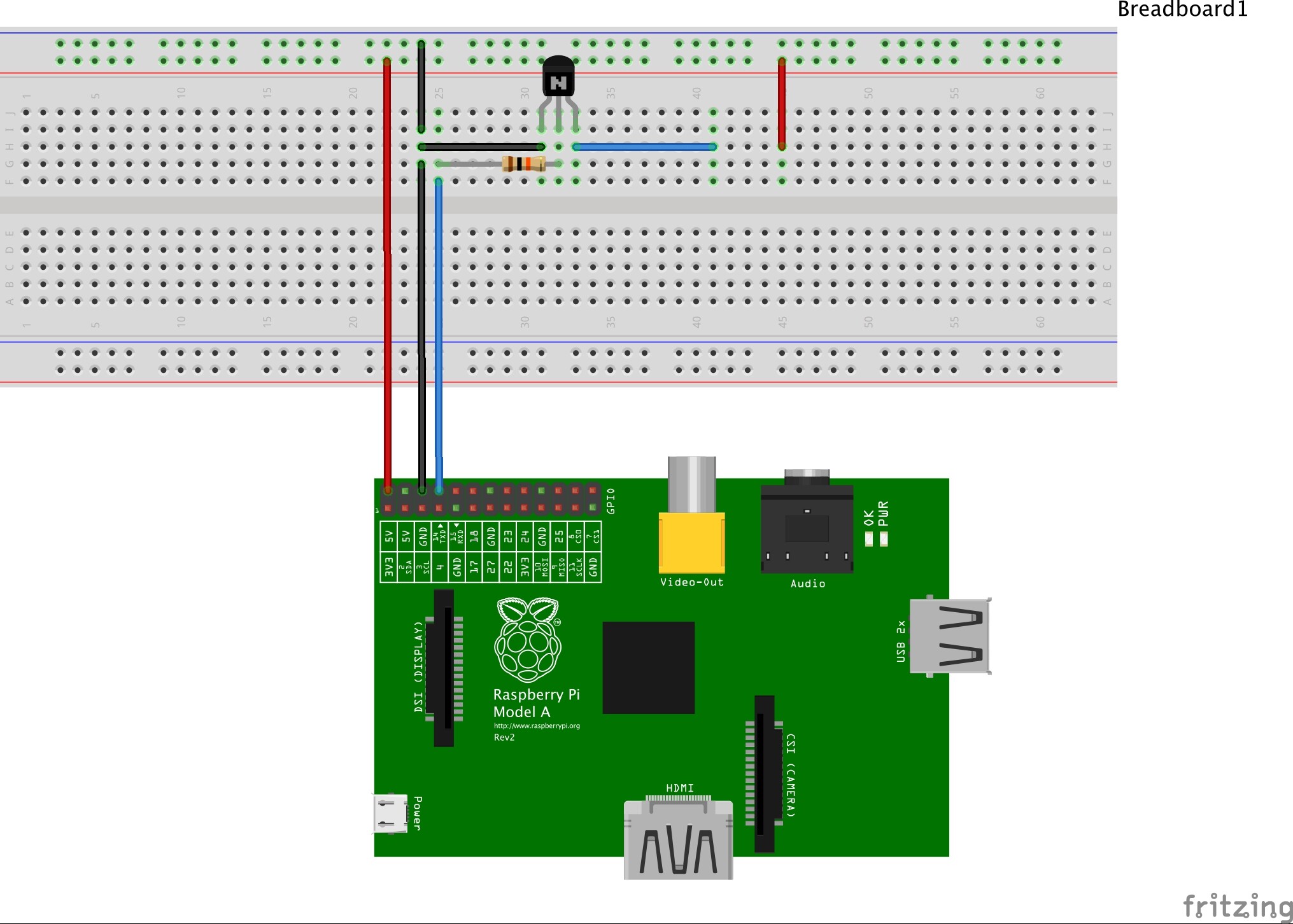
After some tests, I get 3.v to 5V using 2N7000 N-Channel.
I did a connections draw (I used RPi image, I dont get BBB image in my Fritzing).
Does someone can check it for me? is it correct ? My multimeter show 5.5v output
Thanks a lot
Carlos
Hello guys!
It is wrong!!! Does nos working as expected.
Does someone could instruct me how todo this ? 3v to 5 using 2n7000 …
Thank you!
Carlos
Perhaps you can google for “MOSFET as Switch”
I attached my solution. The relay should be connected to the end of the blue line and +5V.
Hello Tux Leonard, thank you by your answer.
Using +5v I had success too, but I would like to usage only +3v and convert it to +5v like this circuit
http://electronics.stackexchange.com/questions/56093/how-to-use-a-3v-output-to-control-a-5v-relay
But I 'm having difficult understand this and simulate with BBB or RPi
If possibe, could you help me pls?
Thank you o much and happy new year for everyone!!!
Carlos
Why don’t you just use a 3 volt relay ?
I have several on order from Digikey.
I am basically doing what you are attempting.
I am driving a 3 volt relay from an I/O port. The trick is to use the Digikey Search feature to look for a 3 volt relay and NOT a 3.3 version.
If you use a 3 volt relay then the Vce voltage drop of the transistor will not affect the relay. (turn on is usually ~2.5v) They also come with built in diodes J
Bill
I am sorry but this is nonsense.
 ?
?