how can I use the Motor Cape in bb ai 64?

well actually I already asked that question in the discord. but I’m really making this post(?) to see if someone can help as well or to make it accessible for future reference (in case it can be solved hahaha).

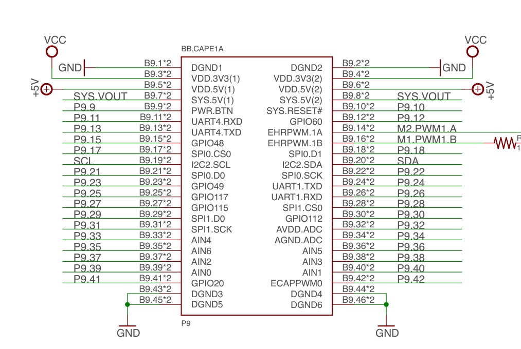
my progress is that when entering the diagram of the motor layer you can actually see which pins are used for gpio and pwm now we just need to see how to do the dtbo.

IF THE CAPE ALREADY EXISTS PLEASE SHARE IT!!!

1 Like

Try looking here

I looked and did not find an old overlay for the motor cape, I did that with load cape thanks to the help of @RobertCNelson pointing me in the correct direction.

No overlay would lead me to an assumption that the default base devicetree already has everything enabled. Might look over the schematic and see exactly what pins are used and go from there.

If you find it you can use a few git commands, I had to look those up, to move into the current branch. It might be better to build it in the official tree, this assumes it might require linking. If it has no linkages just use dtc at cli. It will take some tweaking since that is more than likely for BBB or it will be good starting point.

2 Likes

Hey @crizz ,

Seth here from the forums. Please forgive me. I am very sorry I routed you into thinking I could provide assistance. I remembered briefly of “thoughts” instead of hard evidence that it can work right now.

@foxsquirrel is right. Things are not in the correct manner to port it to the current spec.

Seth

1 Like

dnt worry! im having fun trying to gte the answer xddd

are you suggesting me to do it first for the bbb?

Do you have the exact header pin out for that cape and what ports need to be turned on?

1 Like

Yes, much easier with bbb, it is very well documented and a very stable platform. Once you figure the BBB you just need to do a little magic to get ai-64 up. Unless you are doing some real heavy duty work the BBB is a very good choice.

2 Likes

ok! i think i made a mistake buying first the beaglebone ai 64 xdd

/dts-v1/;
/plugin/;

/ {
    compatible = "ti,beaglebone", "ti,beaglebone-ai-64";

    fragment@0 {
        target = <&am33xxpinmux>;
        overlay {
            pinmuxmotorpins: pinmuxmotorpins {
                pinctrl-single,pins = <
                    0x08C 0x07  /* P8.8 GPIO23 /
                    0x090 0x07  / P8.10 GPIO2_4 /
                    0x094 0x07  / P8.12 GPIO1_12 /
                    0x098 0x07  / P8.14 GPIO0_26 /
                    0x09C 0x07  / P8.13 GPIO0_23 /
                    0x0A0 0x07  / P8.19 GPIO0_22 /
                    0x0C0 0x07  / P9.12 GPIO1_28 /
                    0x0C4 0x07  / P9.15 GPIO1_16 /
                    0x0D4 0x07  / P9.23 GPIO1_17 /
                    0x0D8 0x07  / P9.27 GPIO3_19 /
                    0x0CC 0x07  / P9.14 GPIO1_18 /
                    0x0D0 0x07  / P9.16 GPIO1_19 */
                >;
            };
        };
    };

    fragment@1 {
        target = <&ocp>;
        __overlay {
            motor_gpio {
                compatible = "gpio-of-helper";
                pinctrl-names = "default";
                pinctrl-0 = <&pinmux_motor_pins>;
                status = "okay";
            };
        };
    };

    fragment@2 {
        target = <&epwmss1>;
        __overlay {
            status = "okay";
        };
    };

    fragment@3 {
        target = <&ehrpwm1>;
        __overlay {
            status = "okay";
        };
    };
};

you mean this?

That might be it, the pwm is something needed. I don’t have that cape, to verify anything.
It shows compatible with ai-64 so it might work. You will need it in .dtbo so you can add it in the config the ai-64 uses. I don’t recall the exact name, it is in boot somewhere.

The red flag is it uses am33 pin mux, is that correct???

They are in mode 7 which is an output with pull up, it looks like you have a strong basis for an overlay. Just get the correct node and registers for the AI-64. Without any includes you can use dtc, keep in mind if you have to add any #includes you will have to use the BeagleBoardDevicetree framework. Just drop the .dts in the src folder. $make, if it breaks or you are finished besure to $make clean

idk abut am xdd

and/or…


Those M2.PWM1.A are for the BBB like @foxsquirrel stated but the BBAI-64 may be able to have it in working conditions if the right people get to it. Me, I am out. I can provide shallow data for now…

Seth

1 Like

I’ve gotten the pwm’s for this cape to mostly work, on your bbai64.

voodoo@BeagleTest:/dev/beagle/pwm/P9_16$ uname -r
6.1.83-ti-arm64-r62

Upgrade your system:

sudo apt update
sudo apt-get dist-upgrade -yq

Update Device-tree overlays:

cd /opt/source/dtb-6.1-Beagle/
git pull
./build_n_install.sh

Update /boot/firmware/extlinux/extlinux.conf with:

    fdtoverlays /overlays/k3-j721e-beagleboneai64-BBORG_MOTOR.dtbo

Verify with:

voodoo@BeagleTest:~$ sudo beagle-version | grep UBOOT
UBOOT: Booted Device-Tree:[k3-j721e-beagleboneai64.dts]
UBOOT: Loaded Overlay:[k3-j721e-beagleboneai64-BBORG_MOTOR.kernel]

Enable all pwm symlinks pins:

sudo beagle-pwm-export --pin p8_13
sudo beagle-pwm-export --pin p8_19
sudo beagle-pwm-export --pin p9_14
sudo beagle-pwm-export --pin p9_16

PWM’s are ready for your control:

voodoo@BeagleTest:~$ tree /dev/beagle/pwm/
/dev/beagle/pwm/
├── P8_13 -> /sys/devices/platform/bus@100000/3000000.pwm/pwm/pwmchip0/pwm1/
├── P8_19 -> /sys/devices/platform/bus@100000/3000000.pwm/pwm/pwmchip0/pwm0/
├── P9_14 -> /sys/devices/platform/bus@100000/3020000.pwm/pwm/pwmchip2/pwm0/
└── P9_16 -> /sys/devices/platform/bus@100000/3020000.pwm/pwm/pwmchip2/pwm1/

5 directories, 0 files

Control of the 4 high motor controls:

echo 1 > /sys/class/leds/m1_high/brightness
echo 1 > /sys/class/leds/m2_high/brightness
echo 1 > /sys/class/leds/m3_high/brightness
echo 1 > /sys/class/leds/m4_high/brightness
echo 0 > /sys/class/leds/m1_high/brightness
echo 0 > /sys/class/leds/m2_high/brightness
echo 0 > /sys/class/leds/m3_high/brightness
echo 0 > /sys/class/leds/m4_high/brightness

Regards,

2 Likes

Hello,

Does this work with the 6.6.x kernel?

Seth

P.S. I followed the steps from above but I received an error on kernel 6.6.x with this output:

PWM overlay is missing, did you add it to /boot/firmware/extlinux/extlinux.conf and reboot

Okay and…

I got it to work but not for turning on the LED under PWM for motor controls…

What would I need outside of PWM for controlling the motor (solenoid)?

Seth

P.S. I tried echo and my files are there for shell scripting but I receive no movement so far. Is there a catch I am missing?

Okay…I am seeing progress here on this front!

I got motor_three to have the LED lit on it. I am not plugged into motor_three right now but the red LED lights up!

I am trying to get LED 1/motor_one working so far.

I have some not-so-awesome code to handle the build so far.

Seth

P.S. Please send guidance for motor_one if anyone has time…

Update to Illustrate

So, building with PWM is now available although I have been slow to make it work. It works!

There are a couple tricks but all in all, thank you to anyone who built this idea to make it work!

Seth