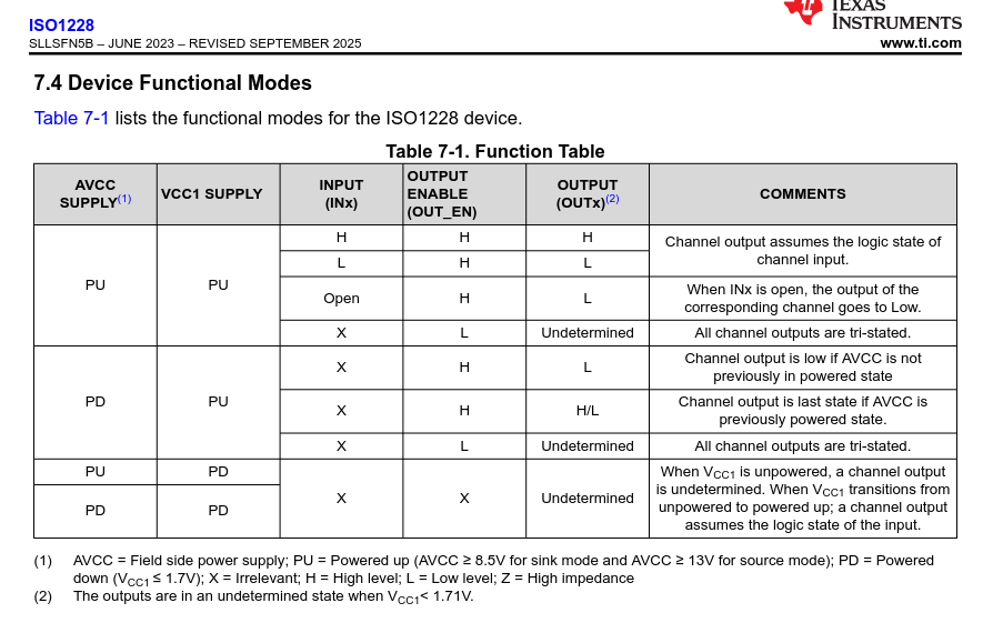
The big issue I see is that this chip says that the non-field side power supply is powered down then the output is undefined → Presumably can’t rely on it not to blow board since I want to respect this
“NOTE: DO NOT APPLY VOLTAGE TO ANY I/O PIN WHEN POWER IS NOT SUPPLIED TO THE BOARD. IT WILL DAMAGE THE PROCESSOR AND VOID THE WARRANTY.
NO PINS ARE TO BE DRIVEN UNTIL AFTER THE SYS_RESET LINE GOES HIGH.”
Would I need to route all the IO pins through some form of normally open switch? Seems wrong, especially if the behavior of that switch is undefined if the power is off
Are most I/Cs not like this and this sort of issue is arising because we could have different power states on each side of isolation barrier?
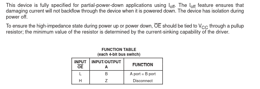
Alright, so I found these TI 244 bus switches, the thing is it looks like they are normally closed instead of normally open, and it mentions pullup resistors and power down safety as you did. So I assume this is the right thing and my understanding is faulty. Like I said I’ve not done PCB design so I apologize if this is basic, maybe by typing this out I will get an understanding.
When we are powered down VCC should be at 0 so we are in the “isolation during power off” state, so we are good.
On power up we want to start at the power down state which is OE high, so tying that pin to power will do that.
The part about the resistor value is because when we actually want to control the switch, we need to pull the voltage value at the pin down to zero, so we can’t have our resistor to VCC over powering that.
If I have all that right: If I were to drive one of these switches off of sys_reset, then I should not need to bother with pulling to VCC because Reset would mean the device is ready?
Or if I did decide to to do the pullup thing, do I have to worry about that driving the pin on startup? Or during startup a pin being undefined low and causing mayhem?
Ahh, I did not see that the ISO1228 has it’s own OE; you can tie that to SYS_RESET.
If you don’t need to read anything back, you can dispense with the MISO pin,
otherwise just run it through a LVC2G241 to make sure it’s undriven when SYS_RESET is low.
Yeah the only thing about the output enable is in that table it says it is irrelevant when the CPU side is unpowered, and all the other entries for the unknown state but that particular one say the undefined is tristated.
Maybe I should ask TI.
In the long term I wanted to know the proper way to connect to the IO and it seems like the bus switch is the answer.
I guess I’ll have do something similar and find out if a given device has known power off state and if not, it will have to go through the bus switch.
Next to figure out my analog pin isolation and conversion to 1.8v