I have been trying to have two Beaglebones communicate with one another using CAN over two Beaglebone Comms Capes, but I am unable to config-pin P9.24 and P9.26 to CAN, as their files are not found. The error I get is : ERROR: open() for /sys/devices/platform/ocp/ocp:P9_24_pinmux/state failed, No such file or directory. I suspect that these pinmux files are not present due to the Comms cape overriding it. I am able to load up can0 and can1, but there is no communication between the two beaglebones. There is no voltage change on the oscilloscope when messages are being sent, meaning the CAN bus has not been set up properly. I wanted to go back to the source code of the DTO, but that page is no longer available. Am i approaching this the wrong way?
Hi @Sozomoto
It is good when posting to tell us what system version you have installed
uname -a
cat /etc/dogtag
To see what overlays have been loaded you can in a terminal do
ls /proc/device-tree/chosen/overlays/
I think the overlay you are looking for is BBORG_COMMS-00A2.dts
This enables CAN and sets the pin muxing. This is included in BeagleBoard.org Debian Bullseye Minimal Image 2023-03-03
To check for the cape look in
/opt/source/dtb-5.10-ti/src/arm/overlays
dtb-5.10-ti will depend on your kernel version.
If you are running a very old system it may predate the inclusion of the overlay.
Does the CAN interface show up in the list of network devices ?
ip -br link
Is it up or down ?
To set the baudrate I have a small script I use as I always forget the command.
#!/bin/bash
sudo ip link set down $1
sudo ip link set $1 type can bitrate $2
sudo ip link set up $1
then run setcan can0 250000 for example to set the baudrate to 250K
I can’t find a schematic for the cape. If it doesn’t have termination resistors fitted, you will need to add them. You need a 120 Ohm resistor at each end of the CAN bus. Only 2 per bus. Using a DVM measure the resistance between CAN high and CAN low with the cape disconnected. It should measure 120 Ohms or 60 Ohms if it is wired to a second cape.
Apologies, the system version I have is: Linux beaglebone3 4.19.94-ti-r42 #1buster SMP PREEMPT Tue Mar 31 19:38:29 UTC 2020 armv7l GNU/Linux, and the Buster IoT Image 2020-04-06. The overlay is found in /proc/device-tree/chosen/overlays/. As for the location of the .dts file, it is not found in /opt/source/dtb-5.4-ti/src/arm/, nor is it found in /opt/source/dtb-4.19-ti/src/arm/ and /opt/source/dtb-4.14-ti/src/arm/. It is, however, found in /opt/source/bb.org-overlays/src/arm/.
My can0 is up on both Beaglebones, as per the following:
can0 UP <NOARP,UP,LOWER_UP,ECHO>. I used your script to set it up. I then ran cansend can0 123#DEADBEEF on one device, and candump can0 on the other, and no message was observed.
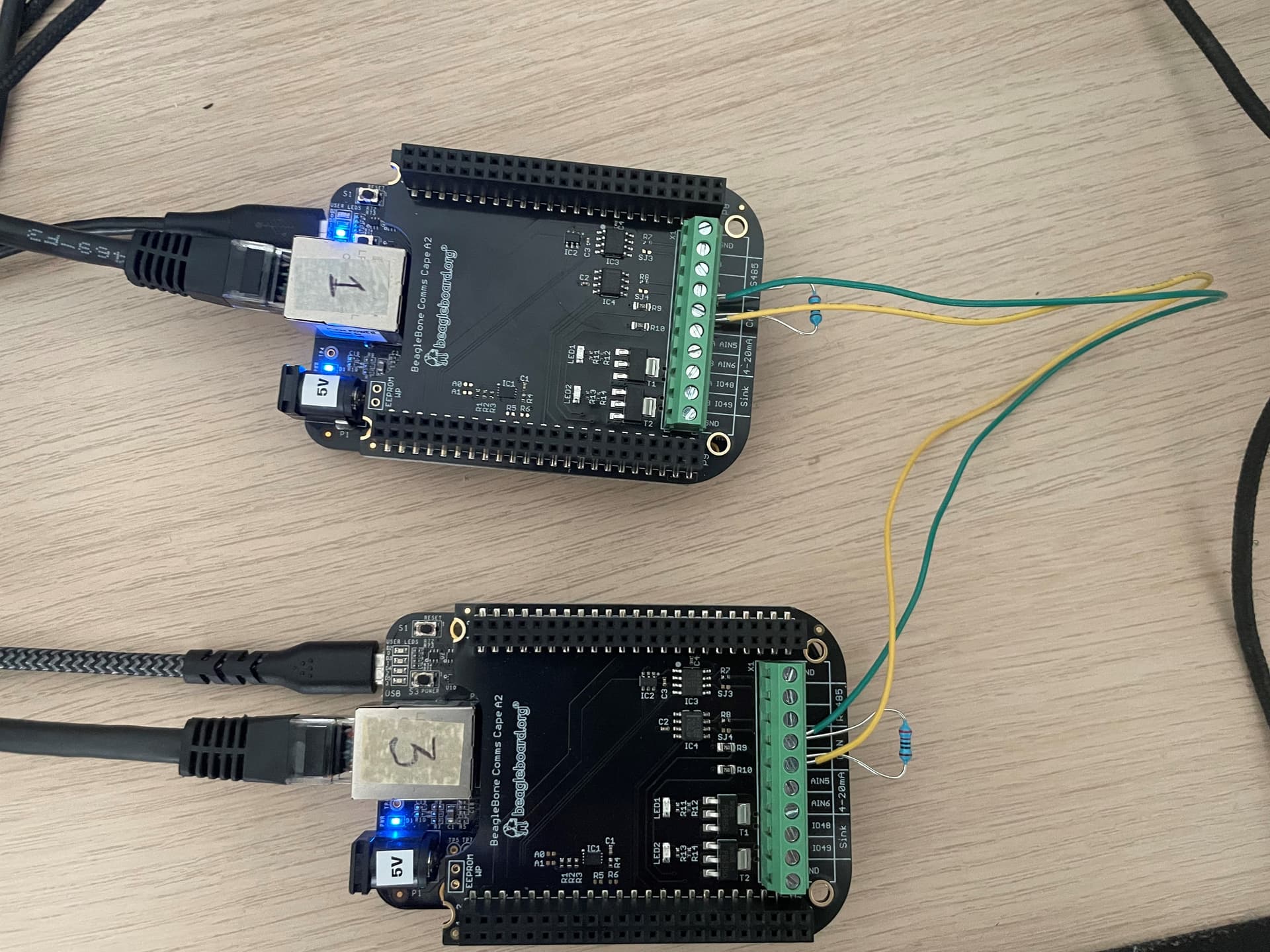
My setup is fairly simple, as shown above. If I were to install the Debian Bullseye Minimal Image, would that solve the issue?
Try connecting gnd between the 2 boards. While CAN is a 2 wire bus, you still need a common gnd between the systems.
All CAN transceivers I have seen also have an enable/standby pin. Can’t tell from the photo if the Comms cape has it permanently enabled. It could be tied to a gpio. Did you check can tx on the header pin ?
It wouldn’t hurt to upgrade if all else fails