Hey You and You All Too,
So, here:

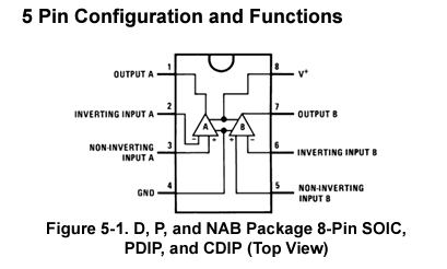
This is from a TI datasheet of the LM358N package that I “will be” using to test out a machine from the BBB and/or BeagleY-AI (if I can get the coprocessors working). I have found, thanks to Ben, a set of gcode parser and pin-conf types for the am335x and BBB/BBG.
Anyway and this is how little I understand right now:
- Is there only one output or are there two outputs to the LM358N package. I see the photo from above in the picture but I am lacking concepts for using the build…
- There are documented scenarios for using the LM358N package.
- Output A and Output B are outputs from what I understand but how would you go about connecting them?
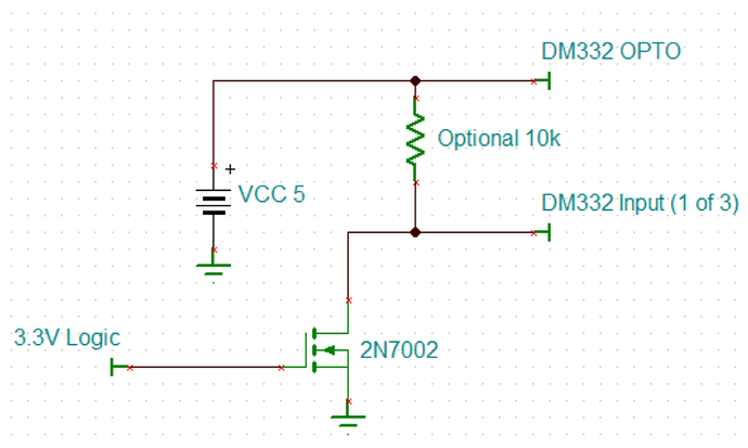
So, the build from what was described to me was for a 2N7002 and with a single output.
Here is what I recorded from Ron from TI:
This fellow, Ron, was nice enough to make me understand the simplicity of some circuits and how I can use CMOS/am335x technology with other amplified circuitry. Phew.
Seth
P.S. I was going to connect some motors and test the gcode parser tonight but it is late now. If you have any recommendations for the coprocessors on the AM67A or using the lib. in question, please give at will!
The lib. in question compiled and did so in a timely fashion which was odd. I can get the source to run and show data as output (mostly errors). The errors are due to my small build frame and the .gcode file not being within the “build frame.”
