Hello,
Issue: LIS2DUX12 sensor is not detected on I2C bus in BeagleV Ahead (TH1520 SoC).
Steps Tried:
-
Connection:
|P9.19 |I2C2_SCL ----> sensor SDA| ==> Connected to Sensor SDA
|P9.20 |I2C2_SDA ----> sensor SCL| ==> Connected to Sensor SCL.
|P9.03 |VOUT_3V3 -----> sensor VCC|
|P9.02 GND|-----> sensor GND|
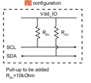
Sensor VIO ---> 10K resistor --> sensor SDA
Sensor VIO ---> 10K resistot --> sensor SCL
-
Checked I2C availability: ls /sys/class/i2c-adapter/i2c-*/
Could see i2c-0, i2c-1, i2c-2, i2c-3, i2c-4, i2c-5, i2c-6 classes are available.
-
Executed I2C scan: `i2cdetect -y 1 (tried 0, 2,3,4 and 5 as well)
We observed only blank grid lines, and no address was detected.
-
Verified I2C driver: modprobe i2c-dev
We could see there is no response on the terminal
-
Verified device nodes in /dev/i2c-*
We observed i2c-0 to till i2c-6 are available
-
dmesg | grep -i i2c
beagle@BeagleV:/$ dmesg | grep -i i2c
[ 2.199533] dwhdmi-light ffef540000.dw-hdmi-tx: registered DesignWare HDMI I2C bus driver
[ 2.464557] i2c /dev entries driver
[ 3.288010] aw87519_pa 5-0058: aw87519_i2c_probe: rst request failed
-
lsmod | grep -i i2c
No logs. Means, we couldn’t see any module information displayed.
-
Kernel version:
beagle@BeagleV:/$ uname -r
5.10.113-g52fbe8443ea1-dirty
-
Device tree configuration is as below:
i2c2 = “/soc/i2c@ffec00c000”;
i2c@ffec00c000 {
compatible = “snps,designware-i2c”;
reg = <0xff 0xec00c000 0x00 0x4000>;
interrupt-parent = <0x12>;
interrupts = <0x2e>;
clocks = <0x15>;
clock-frequency = <0x61a80>;
ss_hcnt = [01 04];
ss_lcnt = [00 ec];
fs_hcnt = [00 37];
fs_lcnt = [00 42];
fp_hcnt = [00 14];
fp_lcnt = [00 1a];
hs_hcnt = [00 09];
hs_lcnt = [00 11];
status = “okay”;
#address-cells = <0x01>;
#size-cells = <0x00>;
phandle = <0x1f5>;
};
Any additional assistance in resolving this issue would be greatly appreciated. Thank you in advance!
NOTE: Similar behaviour is oberserved with BeagleBone Black as well.
So, out of all that testing, did you try to attach a scope to SDA/SCL and see if there’s anything going on there at all?
Oh! My question was for the OP, not you @foxsquirrel.
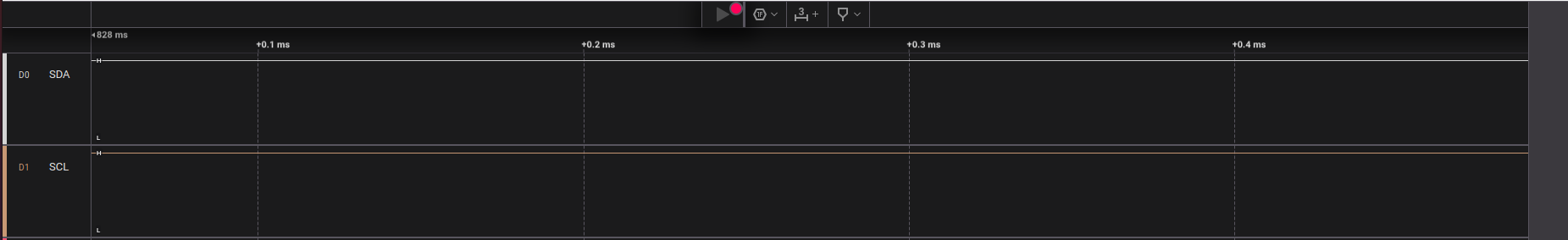
Hi, Thanks for the ask. Yes, we have tested with a logic analyser. There is no out put observed in the GUI. (means, there is no signal is being sent from BeagleV ahead to Sensor SDA/SCL).
NOTE: Similar behaviour is oberserved with BeagleBone Black as well.
Well, to be honest I’m not familiar with the Ahead, but what normally happens when people can’t make special peripherals work, is that the PINMUX registers are set to the wrong function.
If you can drop the SCL line with a gpioset $(gpiofind p9.19)=0
then the function is set to MODE 7, which isn’t what you want.
All this PINMUXing can be a little convoluted, seeing how it keeps coming up,
but a resent thread discusses this point at length and can be found here.
You can also go to the device-trees for the BBB and find inspiration for what you need.
Also, the 10K pullup resistors might be a little weak for your application,
depending how much load they’re going to be up against.
I’m thinking a 2.7K value might be better as a starting point.
As @foxsquirrel correctly did point out before he deleted his post,
it looks like you swapped SDA/SCL on your sensor device; I2C is a multi-point bus,
meaning that every SCL should be connected to every other SCL pin and vice versa,
as opposed to SPI where you do need to swap MISO/MOSI.
Hi, Thanks for the quick reply.
We tried executing the above command. The output is as below.
beagle@BeagleV:~$ gpioset $(gpiofind p9.19)=0
gpioset: at least one GPIO line offset to value mapping must be specified
We have tried with 2.7k resistor, but still no luck.
Actually, there was a typo mistake. We are connecting the sensor to the beagleV ahead in a correct way.
|P9.19 |I2C2_SCL ----> sensor SCL| ==> Connected to Sensor SCL
|P9.20 |I2C2_SDA ----> sensor SDA| ==> Connected to Sensor SDA.
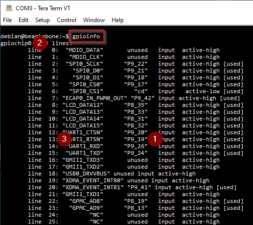
Good good, we’ll go the gpioinfo route instead:
so in this example the information we need is marked by numbers 2 and 3:
gpioset 0 13=[0|1].
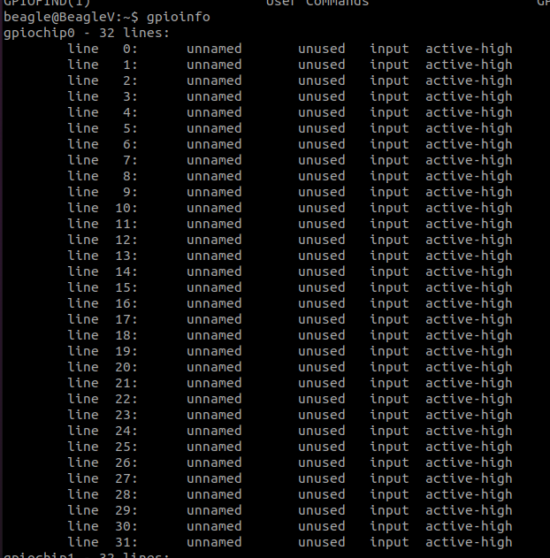
We have executed the “gpioinfo” command and observed the output below.
beagle@BeagleV:~$ gpioinfo
gpiochip0 - 32 lines:
line 0: unnamed unused input active-high
line 1: unnamed unused input active-high
line 2: unnamed unused input active-high
line 3: unnamed unused input active-high
line 4: unnamed unused input active-high
line 5: unnamed unused input active-high
line 6: unnamed unused input active-high
line 7: unnamed unused input active-high
line 8: unnamed unused input active-high
line 9: unnamed unused input active-high
line 10: unnamed unused input active-high
line 11: unnamed unused input active-high
line 12: unnamed unused input active-high
line 13: unnamed unused input active-high
line 14: unnamed unused input active-high
line 15: unnamed unused input active-high
line 16: unnamed unused input active-high
line 17: unnamed unused input active-high
line 18: unnamed unused input active-high
line 19: unnamed unused input active-high
line 20: unnamed unused input active-high
line 21: unnamed unused input active-high
line 22: unnamed unused input active-high
line 23: unnamed unused input active-high
line 24: unnamed unused input active-high
line 25: unnamed unused input active-high
line 26: unnamed unused input active-high
line 27: unnamed unused input active-high
line 28: unnamed unused input active-high
line 29: unnamed unused input active-high
line 30: unnamed unused input active-high
line 31: unnamed unused input active-high
Same case with gpiochip1 - 32 lines, gpiochip2 - 32 lines, gpiochip3 - 32 lines,gpiochip4 - 32 lines, and gpiochip5 - 32 lines.
I admit, that does indeed make it a lot harder for us to grasp onto something here.
(and also why gpiofind doesn’t go anywhere)
@lorforlinux, I see your name all over the device-trees for this thing.
Can you help us out here?
I’m used to Beagles at least providing a bit of information, but here we got nothing…
Ok, from what I have been able to glean from here,
the pins we want are on gpiochip2, lines 9 and 10,
so the command to try becomes gpioset 2 [9|10]=[0|1].
If you’re able to wiggle the pin levels with that, the PINMUX is in MODE 3,
explaining why you’re “flat-lining”.
You obviously want MODE 0, but how to get there is beyond me. Deepak?