Hello everyone,
I’m new to this subject but I’m trying to collect temperature data from this sensor : https://www.mikroe.com/thermo-9-click by using Python and a BeagleBone Black Rev C. The BBB is new and I don’t have any SD card so I flashed nothing on it. My problem is that when I connect the sensor (where I moved the resistance to allow I2C mode) the BBB detects nothing : do you have any idea why ? Should I “enable” I2C pins ?
I’ll be grateful if someone can help me.
Best regards,
Hi
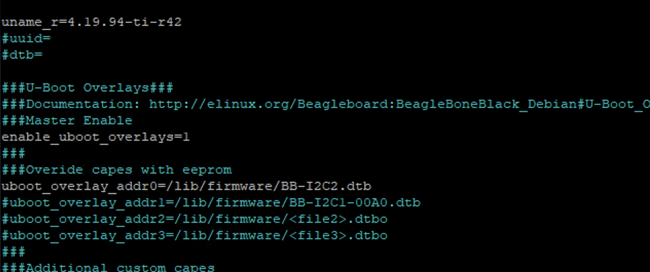
You need to load a dtb to enable the i2c
Edit uEnv.txt file and uncomment #u_boot_overlay_addr1 and add instead .dtbo add BB-I2CX-00A0.dtb where x is the i2c 1 or 2 according the port you are using.
Astrid:
I debugged an I2C bus just recently - I had 3 devices, a DS3231 real time clock, a BME680 environmental sensor and a BNO055 inertial motion unit. I had a lot of trouble with the last one.
Two suggestions:
First, use the i2cdetect and i2cdump utilities. The basic commands to check i2C bus 2 (pins P9_19 and P9_20) are:
I2cdetect -l
I2cdetect -r 2
You can google "i2cdetect BBB” to find more info. Using these rules out any problems with Python. If your device is not showing up, check your wiring. If it is showing up and i2cdump works too, then you may want to check the python libraries.
Second, if you have access to an oscilloscope, use it to check SDA and SCL. My BNO was appearing in i2cdetect and working intermittently in Python. When I looked at it with the ’scope, it was clear that low to high transitions on SDA where taking far too long. A 1KΩ pull-up resistor fixed this (add it close to the sensor between SDA and 3V3). If you don’t have a scope, try adding the pull up resistor. My devices each had a 10KΩ pull up, but this was not enough. Be careful that the combined load does not exceed the 6 mA the BBB pins can safely sink.
In case you need it, here’s the full list of python libraries I installed. The first one is included in a fresh install, but check to see if it needs upgrading. You can ignore the last 3 and use the one for your sensor instead. Nothing else is needed. There is a lot of old information still posted; these should work on a fresh install. Note the odd underscore in lis3dh is correct.
sudo pip3 install Adafruit_BBIO -U
sudo pip3 install adafruit_circuitpython-lis3dh
sudo pip3 install adafruit-circuitpython-busdevice
sudo pip3 install adafruit-circuitpython-register
sudo pip3 install adafruit-circuitpython-ds3231
sudo pip3 install adafruit-circuitpython-bme680
sudo pip3 install adafruit-circuitpython-bno055
Hope this helps,
-Steve
Hello Vinicius,
Thank you for your email. I tried what you said but I still detect nothing. Is it the line with addr0 or addr1 that I should change ?
Astrid Hochart
Hi Astrid,
where are you hooking your sensor ? What pins are you using?
19 and 20 as mentioned on the pins description !
You also need pull up resistors on the I2C lines
Hello !
Thank you for your reply. So I need to have a wire from Pin19 to a resistance and then another wire from the resistance to SCL pin of my sensor ? (and same for SDA and pin 20)
Here is the diagram for my i2c device. This shows where the pull-up resistors are added. You will need something similar.
But first check the documentation for the thermo-click to see if it already has pull-up resistors. It may have 2K, 5K, 10K already. Don’t allow the parallel resistance to go below 500 ohms.

I just checked and they already have pull up resistors of 4.7 kohms.
Then it is safe to add 1K. My devices have 10K and did not work until I added the 1K resistors.
I checked in on a scope and adding 1K fixed the waveform.
-Steve
Can it be from the BBB ? Because I tried with another sensor which works via I2C on another MCU and my BBB doesn’t recognize it neither.
If I interpret the confusing schematic from
https://www.mikroe.com/thermo-9-click there appear to already be a pair of
4.7k pull-ups on the board.
I can only speak from my experience. I have three Adafruit sensor breakouts connected on I2C bus 2. Each of these has its own 10K pull-up resistors. The last board did not work until I added an external 1K pull up. It is 100% reliable since then. I have built this twice and experienced the same thing both times. I spent a lot of time chasing software and asking questions on this forum. Five minutes with an oscilloscope showed me the real problem was that high values on the SDA line were not reaching 3.3V before it was sampled. Based on this, a logical next step is to add an external 1K pull up and see what happens.
I tried 1Kohms and 10kohms but I still have nothing unfortunately…
Normally the BBB automatically detects I2C devices right ?