I2C random read of off-board device from within PRU not working correctly

Does anyone know the correct programming sequence for doing an I2C random read from within the PRU? I’ve tried this nicely written driver:

https://github.com/LinuxDroneLab/pru-i2c-lib

It works less than my code does…

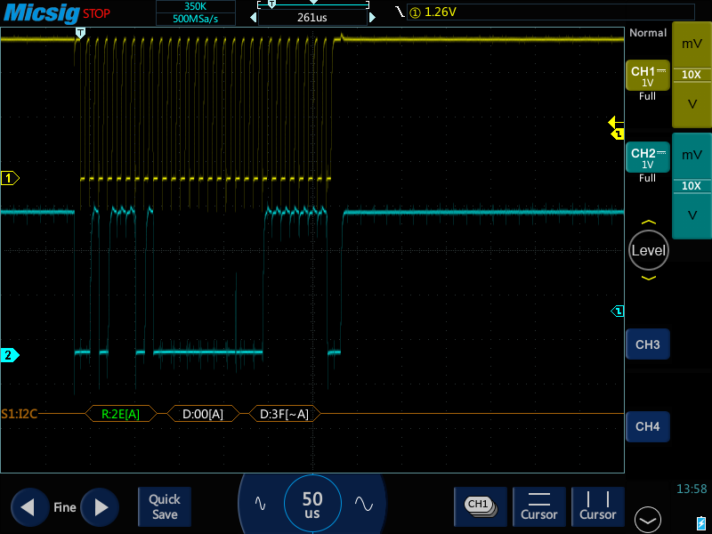
My code works fine if I call my routine once, on the scope I see the write followed by the read of the 2 bytes I want… Call my function again and all I see is the read.

Code and scope grabs attached - the documentation on the I2C module from within the AM335xTRM pdf is shocking and this problem is driving me mad…

/*

  • read_wiper - returns the 2nd byte of a 2-byte read from the specified wiper
  • ‘reg’ contains the write command to read the required wiper
    */
    uint8_t read_wiper(uint8_t reg)
    {

uint8_t dataByte;

//initialise i2c2 device
init_i2c();

//set I2C2_CNT register to 1 for initial write command
I2C2_CNT = 1;

while (!(I2C2_STATUSRAW & 0x0100));
//poll ‘buss free’ bit in I2C2_STATUSRAW register (bit 8) until it is non-zero
//set transmit mode
I2C2_CON = 0x8601;
//load data register with write command
I2C2_DATA = reg;

while (!(I2C2_STATUSRAW & 0x0004));
//poll ‘access ready’ bit in I2C2_STATUSRAW register (bit 4) until it is non-zero
//set byte count to 2
I2C2_CNT = 2;
//set receive mode
I2C2_CON = 0x8403;

while (!(I2C2_STATUSRAW & 0x0008));
//poll ‘receive ready bit’ in I2C2_STATUSRAW register (bit 3) until it is non-zero

dataByte = I2C2_DATA; //first byte is always 0x00

//zero the receive ready bit once we have read the 1st byte into our local variable
I2C2_STATUSRAW |= 0x0008;

while (!(I2C2_STATUSRAW & 0x0008));
//poll ‘receive ready bit’ in I2C2_STATUSRAW register (bit 3) until it is non-zero

dataByte = I2C2_DATA; //second byte is the value we want

//zero the receive ready bit once we have read the 2nd byte into our local variable
I2C2_STATUSRAW |= 0x0008;

while (!(I2C2_STATUSRAW & 0x0100));
//poll ‘buss free’ bit in I2C2_STATUSRAW register (bit 8) until it is non-zero

return dataByte;
}

void init_i2c()
{
/* Enable I2C2 clock signal generation */
while (!(CM_PER_I2C2 & 0x2))
CM_PER_I2C2 |= 0x2;

/*

  • set I2C2_PSC register to 0x0B
  • set I2C2_SCCL register to 0x0D
  • set I2C2_SCCH register to 0x0F
  • set I2C2_CON register to 1000 0110 0000 0000 (0x8600)
  • set I2C2_SA register to 0x2E (address of MCP4641)
    */

I2C2_PSC = 0x000B;
I2C2_SCLL = 0x000D;
I2C2_SCLH = 0x000F;
I2C2_CON = 0x8600;
I2C2_SA = i2cPotAddress;
I2C2_BUF = 0x0000;

}

20180913135820.png

20180913135835.png

I love the TRM documentation its very detailed best to follow its recommended sequences and roll your own code using examples as a template.

I’d look at the i2C slave data sheet carefully especially the timing/setup diagrams.
you have the scope looks like your close.Another idea look for example code for device even if another micro. Looking at it might give you a clue what’s wrong. Last attempt try something quick and simple if you have available no OS barebones one processor I bet your code works on it.

Good Luck

20180913135835.png

20180913135820.png

Got this working with a few code changes:

/*

  • read_wiper - returns the 2nd byte of a 2-byte read from the specified wiper
  • ‘reg’ contains the write command to read the required wiper
    */
    uint8_t read_wiper(uint8_t reg)
    {

uint8_t dataByte;

//initialise i2c2 device
init_i2c();

//set I2C2_CNT register to 1 for initial write command
I2C2_CNT = 1;

while (I2C2_STATUSRAW & 0x1000);
//poll ‘busy bit’ in I2C2_STATUSRAW register (bit 12) until it is zero
//set transmit mode
I2C2_CON = 0x8601;
//load data register with write command
I2C2_DATA = reg;
while (!(I2C2_STATUSRAW & 0x0010));
//poll XRDY bit in I2C2_STATUSRAW register (bit 4) until it is non-zero

//data has transmitted, write 1 to clear the interrupt
I2C2_STATUSRAW |= 0x0010;

while (!(I2C2_STATUSRAW & 0x0004));
//poll ‘access ready’ bit in I2C2_STATUSRAW register (bit 4) until it is non-zero
//set byte count to 2
I2C2_CNT = 2;

//set receive mode
I2C2_CON = 0x8400;

//set start and auto stop condition
I2C2_CON |= 0x0003;

while (!(I2C2_STATUSRAW & 0x0008));
//poll ‘receive ready bit’ in I2C2_STATUSRAW register (bit 3) until it is non-zero

dataByte = I2C2_DATA; //first byte is always 0x00

//data has been received, write 1 to clear the interrupt
I2C2_STATUSRAW |= 0x0008;

while (!(I2C2_STATUSRAW & 0x0008));
//poll ‘receive ready bit’ in I2C2_STATUSRAW register (bit 3) until it is non-zero

dataByte = I2C2_DATA; //second byte is the value we want

//data has been received, write 1 to clear the interrupt
I2C2_STATUSRAW |= 0x0008;

while (!(I2C2_STATUSRAW & 0x0100));
//poll ‘buss free’ bit in I2C2_STATUSRAW register (bit 8) until it is non-zero

//clear all pending interrupts
I2C2_STATUS = 0x7FF;

return dataByte;
}

Note the clearing of pending interrupts after each check and the final clear of the status register (not status_raw) at the end. 5 byte writes now working every time…