config-pin tells me, Current mode for P9_11 is: gpio
Problem:
I am unable to blink LED connected to P9_11, ( or P9_25 on other P9_XX for that matter )
I am able to blink USR[1-3] LED’s without a problem
Code in use:
Replacing USR1 with P9_11 (0x1<<30) in the source does not result in the LED blinking.
( I have confirmed the LED’s are connected the right way and do light up when connected to 3V and GND )
First thing’s first, P9_11 is not connected to the PRUs output or input registers. Try as you may, but this pin is off limits when using the PRU. As a result of that this pin is not defined in “prugpio.h”.
If you go to the git and have a look at that library you will spot that the P9_25 is defined in said file. As a result of that you could connect the LED to the pin. However as you correctly noticed, this pin still does not appear to work and neither do any other pins on P9 even those that are defined in the magical file.
To understand why that is you need to know a bit about how the PRUs registers are connected to the GPIO (or fast IO). It is not very obvious and I personally find that the supposed “tutorials” on this matter are terrible and obscure what is actually happening with a thick layer of abstraction.
Here is a good resource to read more on that https://ofitselfso.com/BeagleNotes/BeagleboneBlackPinMuxModes.php
If I cut myself short your problem is that you haven’t configured the pinmux for your pins. If you look at the bottom of the program, you will see some pragmas. These are special instructions for the compiler that reserve the pin and set the correct pinmux. What you probably didn’t do is change it from the reservation of usr3 to your desired pin.
You can change the pinmux mannually by running the following command on the bone:
config-pin P9_25 pruout
if you wonder pruin is the other mode that makes the pin ready for input
@lopatin Thanks very much for pointing me in the right direction. That #pragma section was essential.
I have my code working now.
On a related note, I suspect the config-pin is broken or not upto date,
Since P9_16 does not show pruout option, but is in fact possible to set it as pruout and have it working with the example code ( with the correct pragma settings ).
$ config-pin -l P9_16

Available modes for P9_16 are: default gpio gpio_pu gpio_pd gpio_input pwm
This is quite peculiar. I didn’t even know that you could use some of these pins.
Maybe it has something to do with reservation? Some pins on P8 cannot be used unless you deactivate hdmi, so perhaps this is something similar? Perhaps it is some cross platform compatibility issue or maybe they just forgot to update something.
In any case, I’d like to thank you for pointing this out. It might come in handy one day.
Could you please share how do you set P9_16 as pruout if config-pin doesn’t list it in available modes?
Also please share your final code which toggles that pin.
Below is the sample code used to get PRU control the P9_16, might be useful for someone else.
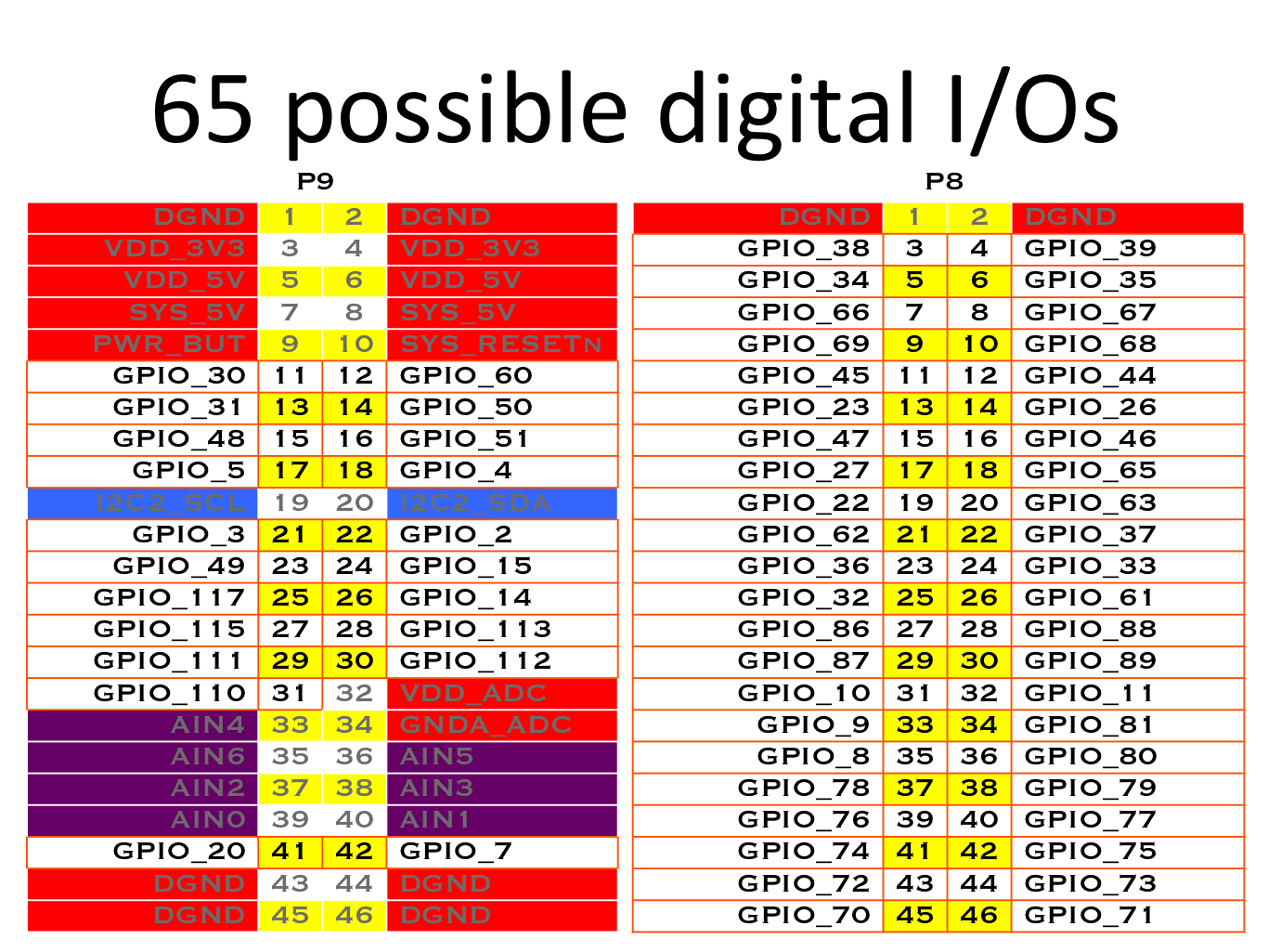
Following the GPIO pin numbering from link below:
#include <stdint.h>
#include <pru_cfg.h>
#include "resource_table_empty.h"
#include "prugpio.h"

volatile register unsigned int __R30;
volatile register unsigned int __R31;

void main(void) {
        // Points to the GPIO port that is used
        uint32_t *gpio1 = (uint32_t *)GPIO1;

        /* Clear SYSCFG[STANDBY_INIT] to enable OCP master port */
        CT_CFG.SYSCFG_bit.STANDBY_INIT = 0;

        while(1) {
                gpio1[GPIO_SETDATAOUT]   = P9_16;       // Turn the USR1 LED on
                __delay_cycles(500000000/5);            // Wait 1/2 second
                gpio1[GPIO_CLEARDATAOUT] = P9_16;       // Off
                __delay_cycles(500000000/5);
        }
        __halt();
}


// Set direction of P9_16 (which is port 1 pin 18)
#pragma DATA_SECTION(init_pins, ".init_pins")
#pragma RETAIN(init_pins)
const char init_pins[] =
        "/sys/class/gpio/gpio51/direction\0out\0" \
        "/sys/devices/platform/ocp/ocp:P9_16_pinmux/state\0gpio\0" \
        "\0\0";
I was getting no output change on the pin. No clue why, but I changed the code to the one mentioned above and now its working.
Please educate me if I’m missing something.
thanks