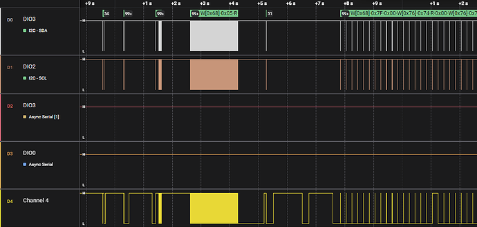
Hi all, I am trying to attach an I2S microphone (SPH0645) to PRU1. On PRU0, I have two I2C devices connected to I2C2 (P9.19 + P9.20), while on PRU1 I am trying to use McASP0 (P8.33 fsr + P8.35 aclkr + P8.36 axr0) to receive I2S audio data. I followed all the steps in the TRM and McASP guide but something weird happens. The AXR0 pin seems to “follow” the I2C signals (see attached image), and no clocks are generated. I am unsure what causes this, I made sure the pin connections are all correct.
I suspect I am either missing some device tree overlay or there is some constraint I am unaware of regarding using I2C and McASP together. My /boot/uEnv.txt:
#Docs: http://elinux.org/Beagleboard:U-boot_partitioning_layout_2.0

uname_r=5.10.168-ti-r71
#uuid=
#dtb=

###U-Boot Overlays###
###Documentation: http://elinux.org/Beagleboard:BeagleBoneBlack_Debian#U-Boot_Overlays
###Master Enable
enable_uboot_overlays=1
###
###Overide capes with eeprom
uboot_overlay_pru=AM335X-PRU-UIO-00A0.dtbo
uboot_overlay_addr1=bbb-reserve-prumem.dtbo
uboot_overlay_addr2=AM335X-I2C2-400-00A0.dtbo
uboot_overlay_addr3=BB-I2C1-RTC-DS3231.dtbo
uboot_overlay_addr4=BB-SPIDEV1-00A0.dtbo
###
###Additional custom capes
#uboot_overlay_addr4=<file4>.dtbo
#uboot_overlay_addr5=<file5>.dtbo
#uboot_overlay_addr6=<file6>.dtbo
#uboot_overlay_addr7=<file7>.dtbo
###
###Custom Cape
#dtb_overlay=<file8>.dtbo
###
###Disable auto loading of virtual capes (emmc/video/wireless/adc)
#disable_uboot_overlay_emmc=1
disable_uboot_overlay_video=1
#disable_uboot_overlay_audio=1
disable_uboot_overlay_wireless=1
disable_uboot_overlay_adc=1
###
###Cape Universal Enable
enable_uboot_cape_universal=1
###
###Debug: disable uboot autoload of Cape
#disable_uboot_overlay_addr0=1
#disable_uboot_overlay_addr1=1
#disable_uboot_overlay_addr2=1
#disable_uboot_overlay_addr3=1
###
###U-Boot fdt tweaks... (60000 = 384KB)
And the code I use to initialize the McASP0 peripheral:
    CT_CFG.SYSCFG_bit.STANDBY_INIT = 0;

    DELAY_MS(50);

    do {
        (*CM_PER_MCASP_CLKCTRL[0]) |= 2;
        DELAY_MS(50);
    } while(((*CM_PER_MCASP_CLKCTRL[0]) & 0x30000) != 0);

    CT_I2S[0]->GBLCTL   = 0;

    DELAY_US(100);

    CT_I2S[0]->PWRIDLESYSCONFIG_bits.IDLEMODE = 1;

    CT_I2S[0]->RMASK_bits.RMASK     = 0xFFFFFFFF;   // Samples are 18 bits
    CT_I2S[0]->RFMT_bits.RSSZ       = 0xB;          // 24 bits from SPH0645
    CT_I2S[0]->RFMT_bits.RDATDLY    = 1;            // 1 bit data delay with respect to the frame sync for I2S mode
    CT_I2S[0]->RFMT_bits.RRVRS      = 1;            // Receive MSB first
    CT_I2S[0]->AFSRCTL_bits.RMOD    = 2;            // 2 Slot Frames
    CT_I2S[0]->AFSRCTL_bits.FSRP    = 1;            // Receive frame on falling edge

    // For I2S: 2 slots each 24 bits @ 48 kHz = 2.304000 MHz clock needed
    // Just put any clock for now to test
    CT_I2S[0]->AHCLKRCTL_bits.HCLKRDIV = 0;
    CT_I2S[0]->ACLKRCTL_bits.CLKRM     = 1;
    CT_I2S[0]->ACLKRCTL_bits.CLKRDIV   = 10;
    CT_I2S[0]->RTDM_bits.RTDMS         = 1;
    CT_I2S[0]->RINTCTL                |= 0xFF;  // Enable all interrupts
    CT_I2S[0]->RCLKCHK_bits.RPS        = 0;
    CT_I2S[0]->RCLKCHK_bits.RMAX       = 0xFF;
    CT_I2S[0]->RCLKCHK_bits.RMIN       = 0x00;

    CT_I2S[0]->SRCTL_0_bits.SRMOD       = 2;
    CT_I2S[0]->SRCTL_0_bits.DISMOD      = 2;

    // Configure as MCASP pins
    CT_I2S[0]->PFUNC_bits.AFSR      = 0;
    CT_I2S[0]->PFUNC_bits.AHCLKR    = 0;
    CT_I2S[0]->PFUNC_bits.AFSR      = 0;
    CT_I2S[0]->PFUNC_bits.AFSR      = 0;

    CT_I2S[0]->PDIR_bits.AFSR   = 1;    // Frame siync clock as output
    CT_I2S[0]->PDIR_bits.AHCLKR = 1;    // HF Clock output (unused)
    CT_I2S[0]->PDIR_bits.ACLKR  = 1;    // Bit Clock output
    CT_I2S[0]->PDIR_bits.AXR    = 0;    // Data pins as input

    // Start clocks
    while(!(CT_I2S[0]->GBLCTL & 0x02)){
        CT_I2S[0]->GBLCTL = 0x2; // Hold RHCLKRST at 1 while rest at 0;
        DELAY_US(50);
    }

    while(!(CT_I2S[0]->GBLCTL & 0x02)){
        CT_I2S[0]->GBLCTL_bits.RCLKRST = 1; // Hold RCLKRST at 1 while leaving rest as-is;
        DELAY_US(50);
    }
Where CT_I2S is an array (size 2) of pointers to the MCASP0 and 1 peripherals; I made a register mapping to access the registers and their bits (did something similar for I2C on PRU0). Similarly CM_PER_MCASP_CLKCTRL is an array size 2 pointing to the Clock module registers of the McASP peripherals.
