Hello, I built a board really similar to beagleboard rev4 from scratch. I just added some USB ports and other few changes.(buy the components, manufacture it, design the layers…etc)
After some problems I finally got a “40W” in the terminal connected to UART3. I could not boot from SDCard because, despite the voltage in VMMC1 is 3V, my WP, DAT[3-0] and CMD pins have a strange voltage value. The voltage values measured in the SDCard reader are shown in this table:
MY BEAGLE | | ORIGINAL BEAGLE | | | | | |
- | - | - | - | - | - | - | - |
0.5 V | | 1.8 V | WP | | Conected to OMAP | | |
1.8 V | | 1.8 V | CD | | Conected to TPS65950 | | |
0.51 V | | 3 V | DAT1 | | Conected to OMAP | | |
0.507 V | | 3 V | DAT0 | | Conected to OMAP | | |
0 V | | 0.078 V | DAT7 | | Conected to OMAP | | Powered by VSIM |
0 V | | 0 V | GND | | | | |
0 V | | 0.072 V | DAT6 | | Conected to OMAP | | Powered by VSIM |CLK | | Conected to OMAP | | |
3 V | | 3 V | VDD | | | | |
0 V | | 0 V | GND | | | | |
0 V | | 0.072 V | DAT5 | | Conected to OMAP | | Powered by VSIM |
0.5 V | | 3 V | CMD | | Conected to OMAP | | |
0 V | | 0.073 V | DAT4 | | Conected to OMAP | | Powered by VSIM |
0.513 V | | 3 V | DAT3 | | Conected to OMAP | | |
0.507 V | | 3 V | DAT2 | | Conected to OMAP | | |
After check the voltages in a real beagleboard I found that DAT[0-3] and CMD are 3V. I have been searching a lot but I could not find why my voltage values are wrong.
The hardware configuration is the same as the original beagleboard: to power OMAP3530 I am using TPS65950. The only difference is that due to a design fail I needed to cut the connection of VMMC1 with the TPS65950 and I am powering VMMC1 with an external source (3V). I took care of give power to VDD in the card reader and to VDDS_MMC1 in the OMAP3530.
VSIM is 0V after reset despite VAUX12S is powered at 3.6V. I could not load any loader into the board yet. If I can not fix MMC problems I will try to boot from UART, because of the 40W it seems that the OMAP processor is alive.
Really thanks.
PD:
-
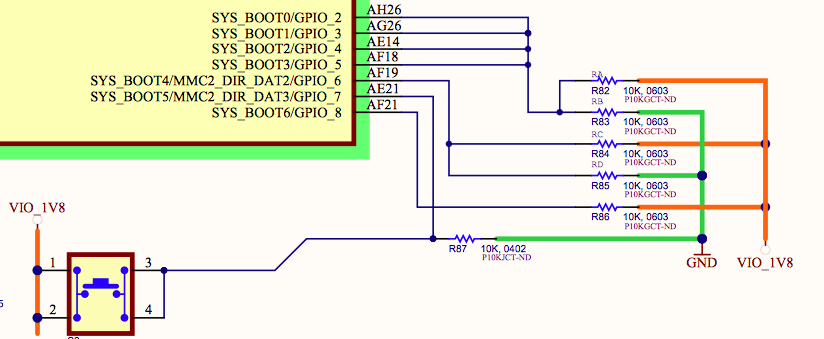
Because all the wrong voltages in my board are almost the same value (0.5 V) I thought that maybe the original beagleboards comes with a different preconfigured pins state-after-reset (pull-down or something) than the OMAP3530 bought directly???
-
Can I say that VMMC1 is reaching correctly the VDDS_MMC1 pin in the OMAP3530 because of the 0.5V in the pins? or the connection between VMMC1 and VDDS_MMC1 could be cut despite the 0.5V?